Hello ROS Developers!
In this post, we start summarizing our YouTube video series called “Exploring ROS with a 2 wheeled Robot”. That’s the part #03 and we hope to help you learning this amazing content by another media, our blog posts. Let’s start!
In the last post, we worked a while with XACROs, in order to simplify our robot model. And now we are going to attach a Laser Scan sensor to our model!
If you don’t have a ROSJect with the previous tutorial, just make a copy of this one, which is the source we are about to start from. Let’s go!
The first modification we’ll do goes to the file ~/simulation_ws/src/m2wr_description/urdf/m2wr.xacro, just after the chassis link (should be at line 54)
  <link name="sensor_laser">
    <inertial>
        <origin xyz="0 0 0" rpy="0 0 0" />
        <mass value="1" />
        <xacro:cylinder_inertia mass="1" r="0.05" l="0.1" />
    </inertial>

    <visual>
        <origin xyz="0 0 0" rpy="0 0 0" />
        <geometry>
        <cylinder radius="0.05" length="0.1"/>
        </geometry>
        <material name="white" />
    </visual>

    <collision>
        <origin xyz="0 0 0" rpy="0 0 0"/>
        <geometry>
        <cylinder radius="0.05" length="0.1"/>
        </geometry>
    </collision>
    </link>

    <joint name="joint_sensor_laser" type="fixed">
    <origin xyz="0.15 0 0.05" rpy="0 0 0"/>
    <parent link="link_chassis"/>
    <child link="sensor_laser"/>
  </joint>
Check that we have a new macro being called, a function for generatin cylinder description for URDF. We have added a new link, to represent the laser scan, as every link, it contains inertial, visual and collision attributes. Finally, a joint to bind it to the root link, the chassis.
In order to have it working, let’s go to the second file: ~/simulation_ws/src/m2wr_description/urdf/macros.xacro. At line 36, lets add the following code (to describe our cylinder macro):
<macro name="cylinder_inertia" params="mass r l">
  <inertia  ixx="${mass*(3*r*r+l*l)/12}" ixy = "0" ixz = "0"
            iyy="${mass*(3*r*r+l*l)/12}" iyz = "0"
            izz="${mass*(r*r)/2}" />
</macro>
Let’s check it in RViz!
Go to a web shell and execute:
user:~$ roslaunch m2wr_description rviz.launch
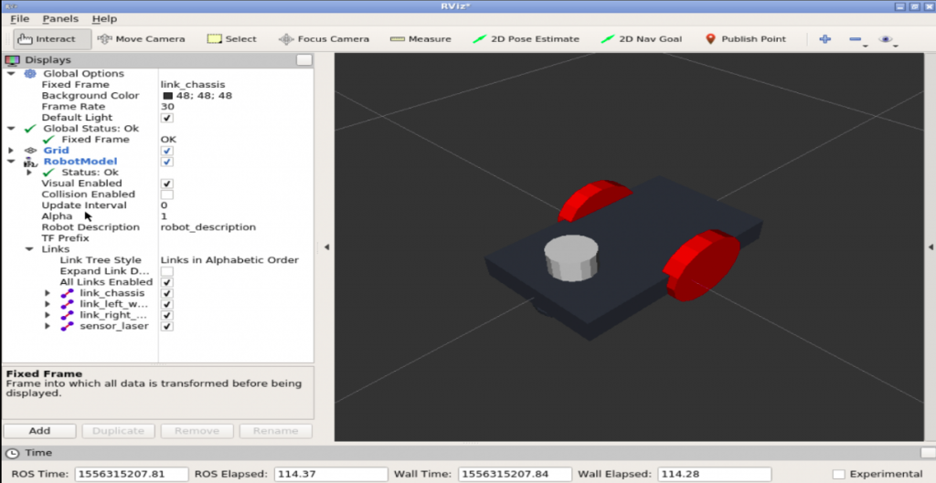
Open the graphical tools, you must have something like this:
So we have a white part on the robot that represents a laser scan!
Now.. Let’s make it a REAL laser scan (in the simulation, I mean =D )
Go to the last file we are going to modify: ~/simulation_ws/src/m2wr_description/urdf/m2wr.gazebo
Place the code below just after the closing tag of the diff_drive plugin:
  <gazebo reference="sensor_laser">
    <sensor type="ray" name="head_hokuyo_sensor">
      <pose>0 0 0 0 0 0</pose>
      <visualize>false</visualize>
      <update_rate>20</update_rate>
      <ray>
        <scan>
          <horizontal>
            <samples>720</samples>
            <resolution>1</resolution>
            <min_angle>-1.570796</min_angle>
            <max_angle>1.570796</max_angle>
          </horizontal>
        </scan>
        <range>
          <min>0.10</min>
          <max>10.0</max>
          <resolution>0.01</resolution>
        </range>
        <noise>
          <type>gaussian</type>
          <mean>0.0</mean>
          <stddev>0.01</stddev>
        </noise>
      </ray>
      <plugin name="gazebo_ros_head_hokuyo_controller" filename="libgazebo_ros_laser.so">
        <topicName>/m2wr/laser/scan</topicName>
        <frameName>sensor_laser</frameName>
      </plugin>
    </sensor>
  </gazebo>
Take a look at the code. Notice that we are describer there the frameName and topicName. They are important in order to visualize it in RViz and, of course, program the robot.
Other important attributes you can tune for your application are: range, scan and update_rate. Feel free to explore it. Don’t miss the official documentation from gazebo!
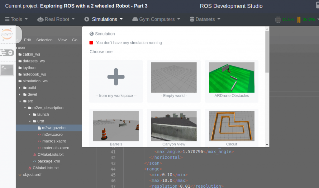
Great, let’s launch a simulation with the robot and its Real Laser Scan! I’ll start a world of my choice, the one barrels, so I can check the laser readings easily. You can play with other worlds further. Go to the simulations tab and choose one:
Now, spawn the robot from the terminal:
user:~$ roslaunch m2wr_description spawn.launch
And check the robot there:
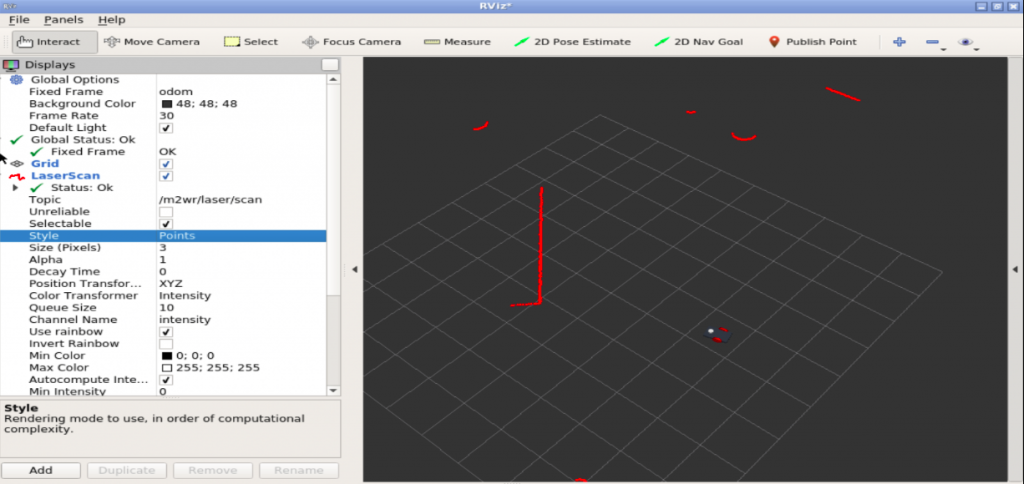
You can “echo” the topic /m2wr/laser/scan to check data coming from the laser. Of course it won’t make much sense in the terminal. So let’s check in RViz. Once more to the terminal, run:
user:~$ roslaunch m2wr_description rviz.launch
Configure RViz to visualize the RobotModel and the LaserScan (check the following image):
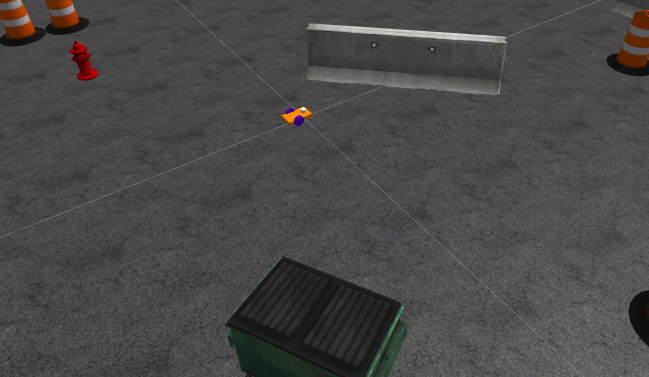
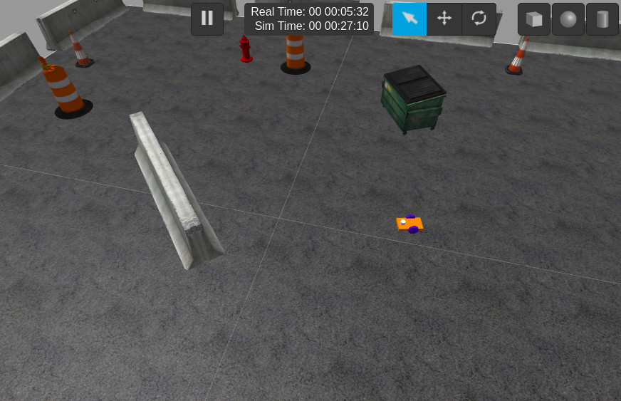
In order to compare, let’s check the robot and world obstacles in gazebo:
Amazing! Isn’t it?
Don’t forget to leave a comment, ask for help your suggest your ideas!
If something went wrong in your ROSJect during the post reading, you can copy mine by clicking here, it’s ready to use!
In the next post, we will start using the data from the LaserScan. Let’s make the robot navigate around the world!
Cheers!





0 Comments