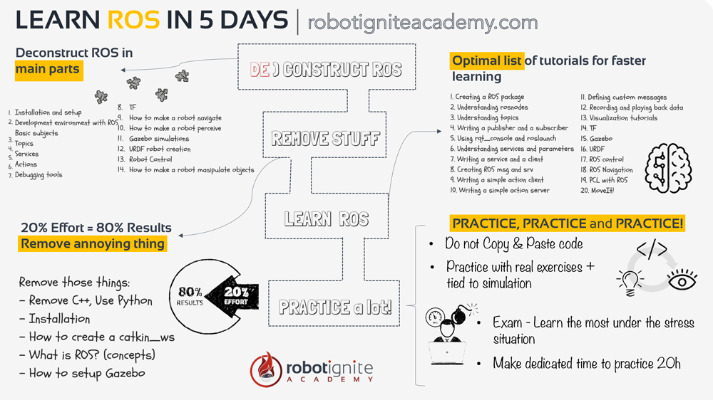
ROS for Beginners: How to Learn ROS

ROS for Beginners: How to Learn ROS

Now is the moment to start learning ROS.

We find many people that are new to ROS lack the basic skills necessary to start programming in ROS. That is why we have included a section of prerequisites here that you must meet before trying to get into ROS.

PREREQUISITES

You need to know in advance how to program in C++ or Python. Also, you need to be comfortable using the Linux shell. Those two are mandatory! If you still don’t know those two, I recommend you start learning how the Linux shell works and then move on to learning how to code in Python. If you don’t know C++, then do not worry about it now. Just learn Python and the Linux shell. We recommend the following free online courses:

As I already mentioned, ROS can be programmed with C++ or Python. However, if you don’t know C++ very well, do not try to get into ROS with C++. If that is your situation, please learn ROS with Python. Of course, you can start learning C++ now because C++ is the language used in the robotics industry, and you will need to make the transition from ROS Python to ROS C++ later. But your initial learning of ROS should be done by programming in Python. I know you are going to think that you can handle it and take both things at the same time. I do not agree at all. Bad decision. Good luck. Final comment: bindings for other languages, like Prolog, Lisp, Nodejs, and R, also exist. Find a complete list of currently supported languages here. I do not recommend for you to learn ROS with any of those languages though. ROS is complicated enough withuot having to complicate it further with experimental languages. Also, you will have plenty of time to practice with those once you know ROS with Python. [irp posts=”12071″ name=”Learn ROS with C++ or Python?”]

LEARNING ROS

If you have the basics of programming in any of those languages and of the use of the shell, the next step is to learn ROS. In order to do that, you have 5 methods to choose from.

Want to Master ROS and Launch Your Robotics Career?

We introduce you to the Robotics Developer Masterclass—your complete guide. This 6-month program will help you master robotics development from scratch and Get You 100% Job-ready to work at leading robotics companies.

Five methods to learn ROS

1- The official tutorials: ROS wiki

The official ROS tutorial website provided by Open Robotics, that is, the organization that builds and maintains ROS, is very comprehensive and it is available in multiple languages. It includes details for ROS installation, how-tos, documentation of ROS, etc. and it’s completely free. Just follow the tutorials provided on the ROS Wiki page and get started. This type of tutorial belongs to the traditional academic learning materials. They start by describing concepts one by one, following a well-defined hierarchy. It’s good material, but easy to get lost while reading, and it takes time to grasp the core spirit of ROS.

There is a long list of tutorials there. The list is so big that it can be overwhelming. If you decide to use this method to learn ROS, then we recommend that you follow the order of the tutorials below for optimal learning:

  • Navigating the ROS file system
  • Creating a ROS package
  • Understanding topics
  • Writing publishers and subscribers
  • Examining publishers and subscribers
  • Writing service client
  • Examining service client
  • Creating Msg and Srv
  • Understanding service params
  • Defining custom messages
  • Recording and playing back data
  • ROS TF
  • ROS URDF
  • ROS Control
  • ROS Navigation

learn-ros-in-5-days-robot-ignite-academy

2- Video ROS tutorials

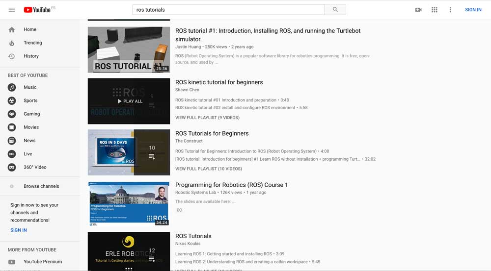
Video tutorials provide a unique presentation that shows how programs are created and run, in a practical way. It allows you to learn how to carry a ROS project from the professional or instructor, which alleviates a beginner’s fear of starting to learn ROS, to a certain degree. There are plenty of ROS tutorials on Youtube. Just search for ROS tutorials and select among all the videos shown.

But there is a drawback, which is that anyone can create a video. There is no requirement for any sort of qualification to publish this content, and therefore, credibility might be shifty. Also, it is difficult to find an order to the videos, so as to provide a full learning path. We only recommend using this method when you want to learn about a very specific subject of ROS. One of the ROS video tutorial courses provided by Dr. Anis Koubaa from Prince Sultan University would be a great starting point for learning ROS. The course combines a guided tutorial, different examples, and exercises with increasing levels of difficulty along with the use of an autonomous robot. Another of the great resources is our YouTube channel. Sorry to mention it like that, but it is true, based on the comments people leave for us! On our channel, we teach about ROS basics, ROS2 basics, Gazebo basics, ROS Q&A, and even real robot projects with ROS. Please have a look at it and let us know if you actually find it useful or not. If you are looking for an answer to a specific ROS question, like How to read laserscan data? How to move a robot to a certain point? or ROS mapping…etc., check out our weekly ROS Q&A series. video-tutorials-ros-learning-methods-fig-2
3- ROS face-to-face training

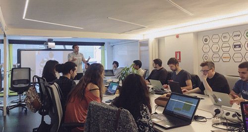
Face-to-face instructional courses are the traditional way of teaching. They builds strong foundations of ROS into students. ROS training is usually a short course, which requires you to focus on learning ROS in a particular environment and period of time. There is interaction with instructors and colleagues. which allows you to get feedback directly. Under the guidance and supervision of instructors, it definitely encourages a better result. The following are some of the institutions that are holding live ROS training or summer courses on a regular basis:

When we talk about ROS face-to-face training, we are not including the conferences, since the learning that you can get there is both little and specific. ROS conferences are more for staying up to date on the latest progress in the field, rather than learning ROS. So, it is supposed that you go to the conferences with at least the minimum ROS knowledge in order to take any profit from them. Some of the ROS conferences around the world:

4- ROS Books

ROS books are published by experienced roboticists. They extract the essence of ROS and present a lot of practical examples. Books are good tools for learning ROS; however, they require a high level of self-discipline and concentration, so as to achieve the desired result. They are only as good as the person using them, and this depends on many factors. It allows for many distractions to easily affect your progress unless a strong sense of self-discipline can ensure that you pay full attention at all times. Here you have a list of ROS books so far:

5- Integrated ROS learning platform – Robot Ignite Academy

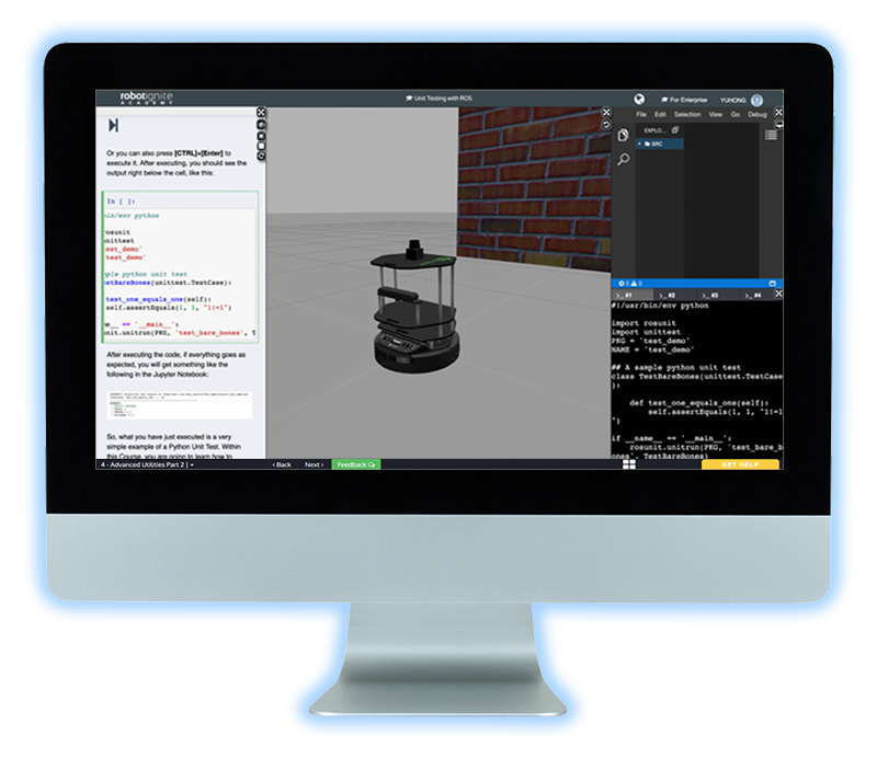
We have created an integrated learning platform as a new way of learning ROS fast. Compared to other learning methods, it provides a more comprehensive learning mechanism. It is the easiest and fastest of all the methods. On the platform, you will learn ROS by practicing on simulated robots. You will follow a step-by-step tutorial and will program the robots while observing the program’s results on the robot simulation in real-time. The whole platform is integrated into a web page, so you don’t have to install anything. You just connect by using a web browser from any type of computer and start learning. Well, perhaps the only drawback is it is not free. You can try the platform with a free account at www.robotigniteacademy.com. We have to tell you that many universities around the world are using this academy to teach their students about ROS and robotics with ROS; for instance, University of Tokyo, University of Michigan, University of Sydney, University of Reims, University of Luxembourg, etc., as well as companies like Softbank, 3M, , and HP.
HOW TO ASK QUESTIONS

It will happen that while learning or creating your own ROS programs, you will have doubts. Things that don’t work as the documentation indicates, strange errors that appear even if you’ve checked that everything is correct… you will need to get support from the community in order to keep improving. For that purpose, you can use two different channels to ask questions:

  • ROS answers: This is the official forum for questions about ROS. Use this forum to ask your technical questions about ROS. Also, you can use it for checking for previous answers to questions similar to yours. Finally, use it to help others by answering the questions that you already know.
  • ROS discourse: This is the second official forum. However, this forum is not about answering technical questions. Instead, it is about announcing things related to ROS. If you have created a new package that interfaces ROS with neural networks, or you are holding an event about ROS, or you are releasing a product about ROS, this is the place to post it. Do not use this forum for technical questions, but for announcements or questions related to the ROS community.

Conclusion

Out of all the methods presented here, I’m going to recommend to you our online Robot Ignite Academy because it is by far the fastest and more comprehensive route for learning ROS. This is not something that I say, but what our customers say. Our online academy has a price, but it will considerably speed up your learning of ROS. In case you don’t want to spend money and you are not in a hurry, then the best option would be to follow the wiki tutorials. They are a little bit outdated and it is a slow path for learning ROS, but they definitely work. After all, that is the method the authors of this guide used to learn ROS. As a final recommendation, besides delivering ROS at the Master of Robotics of LaSalle University, Ricardo delivers a free live online class about ROS every Tuesday at 18:00 CEST/CET (the ROS Developers Live Class). We recommend for you to attend since it is 100% practice-based and deals with a new ROS subject every week.

  Updated on 22 October 2019 

Download ROS Developers Guide

[ROS in 5 mins] 028 – What is Gazebo simulation?

[ROS in 5 mins] 028 – What is Gazebo simulation?

Gazebo is a leader in robot simulation. It is a tool relied upon by hundreds of thousands of users and developers around the world.

Perhaps you have heard “Gazebo simulation” many times, but you don’t know exactly what it is or how it works. In this post, you will learn what a Gazebo simulation is by practicing, as it pertains to ROS development.

You don’t need a ROS installation for this, as we will use the ROS Development Studio (ROSDS), an online platform that provides access to ROS1 & ROS2 computers and other powerful ROS tools within a browser!

Let’s go!

Step 1: Create a Project (ROSject) on ROSDS

Action first before the theory! Grab a copy of the project used for this post using the link below. If you don’t have an account on the ROSDS, you will be guided to create one.

Project link: http://www.rosject.io/l/c40d140/.

Once you have cloned the project, open it up and give it a moment to finish loading.

If you want to know how to install Gazebo in an existing ROS environment on your local computer, then please follow this tutorial:

[irp posts=”8194″ name=”All about Gazebo ROS (Gazebo 9)”]

Step 2: Bring up a Gazebo simulation

From the ROSDS Tools menu, pick the Shell and Gazebo tools. Yeah, we have a tool so named:). Place the tools side-by-side for best effect.

Open Gazebo tools

Type the following commands on the Shell to bring up a Gazebo simulation.

user:~$ roslaunch gazebo_ros mud_world.launch

You should now see something similar to this:

Gazebo Sim Launched

Step 3: What is Gazebo simulation in theory?

Well, I just showed you a Gazebo simulation in the step above, in practice. Now we are going to look what it’s in theory.

  • A Gazebo simulation is a robot simulation made with Gazebo, a 3D simulator with the ability to accurately and efficiently simulate populations of robots in complex indoor and outdoor environments.
  • It’s similar to game engines, but produces better simulations and offers a suite of sensors and interfaces for both users and programs.
  • It has the following main components:
    • World files – contain all the elements in a simulation, including robots, lights, sensors, and static objects. In the image above, the world is shown in the Gazebo app.
    • Models – represent individual elements. The three robots and the object in front of them are models.
    • gzserver – the “work horse” Gazebo program – it reads the world file to generate and populate a world.
    • gzclient – connects to gzserver and visualizes the elements. In the shell output, under “NODES”, we have both gzserver and gzclient listed.
    • gzweb – web version of gzclient, using WebGL.

Step 4: Wrapping up

And that’s it! You know what a Gazebo simulation is in both practice and theory. This knowledge is the foundation for using and creating Gazebo simulations.

Extra: Video

Prefer to watch a video demonstrating the steps above? We have one for you below!

Related Resources and Further Learning

If you are a ROS beginner and want to learn ROS basics fast, we recommend you take any of the following courses on Robot Ignite Academy:

To learn more about Gazebo simulation, visit the full Gazebo Tutorials below:

Feedback

Did you like this post? Do you have questions about what is explained? Whatever the case, please leave a comment on the comments section below, so we can interact and learn from each other.

If you want to learn about other ROS topics, please let us know in the comments area and we will do a video or post about it ?


Edited by Bayode Aderinola & Yuhong Lin

Exploring ROS with a 2 wheeled robot #12 – Bug 2

Exploring ROS with a 2 wheeled robot #12 – Bug 2

Step 0 – Introduction

Yes! We have skipped part number #11. That’s because it was an adjustment from ROS Indigo to ROS Kinetic. It’s not something necessary now, because we have already started using Kinetic.

In this post, we implement Bug 2 algorithm in our existing robot! Let’s use some algorithms we have already done in order to have it all working!

At the end of this post, we’ll have the robot working as shown on the image below:

Step 1 – Importing libraries

We start creating a script file, it goes like that: ~/catkin_ws/src/motion_plan/scripts/bug2.py

(Don’t forget to assign the necessary permissions to the file)

chmod +x ~/catkin_ws/src/motion_plan/scripts/bug2.py

Open the file in the editor and start coding. We start from the necessary libraries:

#! /usr/bin/env python

# import ros stuff
import rospy
# import ros message
from geometry_msgs.msg import Point
from sensor_msgs.msg import LaserScan
from nav_msgs.msg import Odometry
from tf import transformations
from gazebo_msgs.msg import ModelState
from gazebo_msgs.srv import SetModelState
# import ros service
from std_srvs.srv import *

import math

Now.. we define some global variables to store the goal and the current status of the robot and algorithm:

srv_client_go_to_point_ = None
srv_client_wall_follower_ = None
yaw_ = 0
yaw_error_allowed_ = 5 * (math.pi / 180) # 5 degrees
position_ = Point()
initial_position_ = Point()
initial_position_.x = rospy.get_param('initial_x')
initial_position_.y = rospy.get_param('initial_y')
initial_position_.z = 0
desired_position_ = Point()
desired_position_.x = rospy.get_param('des_pos_x')
desired_position_.y = rospy.get_param('des_pos_y')
desired_position_.z = 0
regions_ = None
state_desc_ = ['Go to point', 'wall following']
state_ = 0
count_state_time_ = 0 # seconds the robot is in a state
count_loop_ = 0
# 0 - go to point
# 1 - wall following

Like in Bug 1 algorithm, we are storing the state of the robot. I put some description of the states in an Array called state_desc_. There are also 2 new arguments being received: initial_x and initial_y. They are used to restore the robot position in case you want to restart the algorithm. Very useful to test the algorithm many times in a row!


Step 2 – Defining callbacks

Here we define callbacks, the very same as before, no big deal here. But don’t miss this part of the code:

# callbacks
def clbk_odom(msg):
    global position_, yaw_

    # position
    position_ = msg.pose.pose.position

    # yaw
    quaternion = (
        msg.pose.pose.orientation.x,
        msg.pose.pose.orientation.y,
        msg.pose.pose.orientation.z,
        msg.pose.pose.orientation.w)
    euler = transformations.euler_from_quaternion(quaternion)
    yaw_ = euler[2]

def clbk_laser(msg):
    global regions_
    regions_ = {
        'right':  min(min(msg.ranges[0:143]), 10),
        'fright': min(min(msg.ranges[144:287]), 10),
        'front':  min(min(msg.ranges[288:431]), 10),
        'fleft':  min(min(msg.ranges[432:575]), 10),
        'left':   min(min(msg.ranges[576:719]), 10),
    }


Step 3 – Helper functions

The first helper function is change_state. We had one like this in Bug 1, but we have different rules and states now. Let’s check it:

def change_state(state):
    global state_, state_desc_
    global srv_client_wall_follower_, srv_client_go_to_point_
    global count_state_time_
    count_state_time_ = 0
    state_ = state
    log = "state changed: %s" % state_desc_[state]
    rospy.loginfo(log)
    if state_ == 0:
        resp = srv_client_go_to_point_(True)
        resp = srv_client_wall_follower_(False)
    if state_ == 1:
        resp = srv_client_go_to_point_(False)
        resp = srv_client_wall_follower_(True)

We have only 2 states: wall_follower and go_to_point. The different is that we are not driving the robot in a straight line to the desired point, but following the original line. The one from the initial position to the desired one. This will be implemented on the main function.

The next one: distance_to_line:

def distance_to_line(p0):
    # p0 is the current position
    # p1 and p2 points define the line
    global initial_position_, desired_position_
    p1 = initial_position_
    p2 = desired_position_
    # here goes the equation
    up_eq = math.fabs((p2.y - p1.y) * p0.x - (p2.x - p1.x) * p0.y + (p2.x * p1.y) - (p2.y * p1.x))
    lo_eq = math.sqrt(pow(p2.y - p1.y, 2) + pow(p2.x - p1.x, 2))
    distance = up_eq / lo_eq

    return distance

This function is used to calculate the distance of the robot to the initial line. Super important for this algorithm and it’s used all the time during its execution.

Finally, we’ll use again the normalize_angle function:

def normalize_angle(angle):
    if(math.fabs(angle) > math.pi):
        angle = angle - (2 * math.pi * angle) / (math.fabs(angle))
    return angle


Step 4 – The core of it all!

Let’s check the main function

Part 1 – ROS node, callbacks, services and initial state

def main():
    global regions_, position_, desired_position_, state_, yaw_, yaw_error_allowed_
    global srv_client_go_to_point_, srv_client_wall_follower_
    global count_state_time_, count_loop_

    rospy.init_node('bug0')

    sub_laser = rospy.Subscriber('/m2wr/laser/scan', LaserScan, clbk_laser)
    sub_odom = rospy.Subscriber('/odom', Odometry, clbk_odom)

    rospy.wait_for_service('/go_to_point_switch')
    rospy.wait_for_service('/wall_follower_switch')
    rospy.wait_for_service('/gazebo/set_model_state')

    srv_client_go_to_point_ = rospy.ServiceProxy('/go_to_point_switch', SetBool)
    srv_client_wall_follower_ = rospy.ServiceProxy('/wall_follower_switch', SetBool)
    srv_client_set_model_state = rospy.ServiceProxy('/gazebo/set_model_state', SetModelState)

    # set robot position
    model_state = ModelState()
    model_state.model_name = 'm2wr'
    model_state.pose.position.x = initial_position_.x
    model_state.pose.position.y = initial_position_.y
    resp = srv_client_set_model_state(model_state)

    # initialize going to the point
    change_state(0)

    rate = rospy.Rate(20)

This is something necessary, the same standard we have been doing so far.

Part 2 – The loop logic

    while not rospy.is_shutdown():
        if regions_ == None:
            continue

        distance_position_to_line = distance_to_line(position_)

        if state_ == 0:
            if regions_['front'] > 0.15 and regions_['front'] < 1:
                change_state(1)

        elif state_ == 1:
            if count_state_time_ > 5 and \
               distance_position_to_line < 0.1:
                change_state(0)

        count_loop_ = count_loop_ + 1
        if count_loop_ == 20:
            count_state_time_ = count_state_time_ + 1
            count_loop_ = 0

        rospy.loginfo("distance to line: [%.2f], position: [%.2f, %.2f]", distance_to_line(position_), position_.x, position_.y)
        rate.sleep()

We are all the time calculating the distance to the original line. Depending on the presence of obstacles, we switch between wall_follower and go_to_point.

The point to be used as goal is always the nearest in the line.

Step 5 – Launch it!

Let’s create a launch file and see it working!

Create a new file at ~/catkin_ws/src/motion_plan/launch/bug2.launch. The content is:


<?xml version="1.0" encoding="UTF-8"?>

<launch>
    <arg name="initial_x" default="0" />
    <arg name="initial_y" default="8" />
    <arg name="des_x" default="0" />
    <arg name="des_y" default="-4" />
    <param name="initial_x" value="$(arg initial_x)" />
    <param name="initial_y" value="$(arg initial_y)" />
    <param name="des_pos_x" value="$(arg des_x)" />
    <param name="des_pos_y" value="$(arg des_y)" />
    <node pkg="motion_plan" type="follow_wall.py" name="wall_follower" />
    <node pkg="motion_plan" type="go_to_point.py" name="go_to_point" />
    <node pkg="motion_plan" type="bug2.py" name="bug2" output="screen" />
</launch>

We improved it a little bit. We are restarting our robot position every time we launch it. That’s why we have to new arguments.

1 – You must launch the simulation like we did in previous chapters. Go to the simulation launcher and choose the world configured in our package:

But.. just before, change the world to the previous one we worked before (~/simulation_ws/src/my_worlds/launch/world.launch):

<?xml version="1.0" encoding="UTF-8"?>

<launch>
  <arg name="robot" default="machines"/>
  <arg name="debug" default="false"/>
  <arg name="gui" default="true"/>
  <arg name="headless" default="false"/>
  <arg name="pause" default="false"/>
  <arg name="world" default="world02" />
  <include file="$(find gazebo_ros)/launch/empty_world.launch">
    <arg name="world_name" value="$(find my_worlds)/worlds/$(arg world).world"/>
    <arg name="debug" value="$(arg debug)" />
    <arg name="gui" value="$(arg gui)" />
    <arg name="paused" value="$(arg pause)"/>
    <arg name="use_sim_time" value="true"/>
    <arg name="headless" value="$(arg headless)"/>
    <env name="GAZEBO_MODEL_PATH" value="$(find simulation_gazebo)/models:$(optenv GAZEBO_MODEL_PATH)"/>
  </include>
</launch>


2 – Spawn the robot

roslaunch m2wr_description spawn.launch y:=8

3 – Launch the algorithm

roslaunch motion_plan bug2.launch

Step 6 – Conclusion

Remember! If in any of the steps above you have missed something, you can always clone our ROSJect! Use this link to get your copy: http://www.rosject.io/l/b550d08/

If you like it or have a suggestion to improve it, leave a comment!

See you in the next post!

Exploring ROS with a 2 wheeled robot #7 – Wall Follower Algorithm

Exploring ROS with a 2 wheeled robot #7 – Wall Follower Algorithm

Wall Follower Algorithm

Hello ROS Developers! In this post number #7, as we continue on the track of the video series, we are going to go line-by-line in order to achieve the Wall Follower Algorithm.

In order to start, you can use the ROSject we generate in the previous post, by copying it here.

Our goal is to achieve the following behavior:

  1. Find the wall – Go straight+right until it reaches an obstacle
  2. Turn left, if there is no obstacle in front of the robot
  3. Go straight ahead, if there is an obstacle in the right side

Which is described in the image below:

Exploring ROS with a 2 wheeled robot #7 - Wall Follower Algorithm

Let’s start!


STEP 1

First things first, creating a new script file for the algorithm. I’m calling it follow_wall.py, and  it goes into the folder ~/catkin_ws/src/motion_plan/scripts/.

Some necessary libraries for our script:

#! /usr/bin/env python

# import ros stuff
import rospy
from sensor_msgs.msg import LaserScan
from geometry_msgs.msg import Twist
from nav_msgs.msg import Odometry
from tf import transformations

import math

And just below, our global variables:

pub_ = None
regions_ = {
    'right': 0,
    'fright': 0,
    'front': 0,
    'fleft': 0,
    'left': 0,
}
state_ = 0
state_dict_ = {
    0: 'find the wall',
    1: 'turn left',
    2: 'follow the wall',
}

We are again separating the laser regions (right, front-right, front, front-left and left)
And our state_dict, which defines 3 main states: find the wallturn left and follow the wall

STEP 2

Further, two necessary functions, but no magic or business logic here:

def clbk_laser(msg):
    global regions_
    regions_ = {
        'right':  min(min(msg.ranges[0:143]), 10),
        'fright': min(min(msg.ranges[144:287]), 10),
        'front':  min(min(msg.ranges[288:431]), 10),
        'fleft':  min(min(msg.ranges[432:575]), 10),
        'left':   min(min(msg.ranges[576:713]), 10),
    }

    take_action()


def change_state(state):
    global state_, state_dict_
    if state is not state_:
        print 'Wall follower - [%s] - %s' % (state, state_dict_[state])
        state_ = state

In the callback, we assign the means of the laser reading to the regions we defined
And the change_state is just a formal way to change the state, log and change the value of the variable state_

STEP 3

And now, we define the main function, the one that contains the logic of the wall following algorithm. It’s called here take_action:

def take_action():
    global regions_
    regions = regions_
    msg = Twist()
    linear_x = 0
    angular_z = 0
    
    state_description = ''
    
    d = 1.5
    
    if regions['front'] > d and regions['fleft'] > d and regions['fright'] > d:
        state_description = 'case 1 - nothing'
        change_state(0)
    elif regions['front'] < d and regions['fleft'] > d and regions['fright'] > d:
        state_description = 'case 2 - front'
        change_state(1)
    elif regions['front'] > d and regions['fleft'] > d and regions['fright'] < d:
        state_description = 'case 3 - fright'
        change_state(2)
    elif regions['front'] > d and regions['fleft'] < d and regions['fright'] > d:
        state_description = 'case 4 - fleft'
        change_state(0)
    elif regions['front'] < d and regions['fleft'] > d and regions['fright'] < d:
        state_description = 'case 5 - front and fright'
        change_state(1)
    elif regions['front'] < d and regions['fleft'] < d and regions['fright'] > d:
        state_description = 'case 6 - front and fleft'
        change_state(1)
    elif regions['front'] < d and regions['fleft'] < d and regions['fright'] < d:
        state_description = 'case 7 - front and fleft and fright'
        change_state(1)
    elif regions['front'] > d and regions['fleft'] < d and regions['fright'] < d:
        state_description = 'case 8 - fleft and fright'
        change_state(0)
    else:
        state_description = 'unknown case'
        rospy.loginfo(regions)

We are treating 8 possibilities of the three region readings of the laser (Like in the previous post, but now for a different behavior)

Switch to state Find the wall when:

  1. No obstacles detected
  2. Obstacle on the left side
  3. Obstacles on the left and right sides

For the state Turn left:

  1. Obstacles in front of the robot
  2. Obstacles in front and left of the robot
  3. Obstacles in front and right of the robot
  4. Obstacles in front, left and right of the robot

And finally, we change to the state Follow the wall when:

  1. Obstacle detected only on the right side of the robot

STEP 4

The next thing is to define the behavior of each state:

def find_wall():
    msg = Twist()
    msg.linear.x = 0.2
    msg.angular.z = -0.3
    return msg

def turn_left():
    msg = Twist()
    msg.angular.z = 0.3
    return msg

def follow_the_wall():
    global regions_
    
    msg = Twist()
    msg.linear.x = 0.5
    return msg

This is quite basic, but pay attention to the conventions!! Here we defined to keep the wall on the right side, so if you want to change this convention, you need to play with the signal of the variables. It’s also important it can change depending on the gazebo version and gazebo plugins you are using!! (E.g: During the development of this series, the gazebo version was changed from to 7 and the Z-axis of the driver was changed!)

STEP 5

Finally, we just define our main function, where the main node, publishers, subscribers, and a loop, are defined:

def main():
    global pub_
    
    rospy.init_node('reading_laser')
    
    pub_ = rospy.Publisher('/cmd_vel', Twist, queue_size=1)
    
    sub = rospy.Subscriber('/m2wr/laser/scan', LaserScan, clbk_laser)
    
    rate = rospy.Rate(20)
    while not rospy.is_shutdown():
        msg = Twist()
        if state_ == 0:
            msg = find_wall()
        elif state_ == 1:
            msg = turn_left()
        elif state_ == 2:
            msg = follow_the_wall()
            pass
        else:
            rospy.logerr('Unknown state!')
        
        pub_.publish(msg)
        
        rate.sleep()

if __name__ == '__main__':
    main()

After having it running, you may have the robot going around one of the walls. Don’t forget to spawn the robot near to a wall, or just spawn it anywhere and change its position manually, using Gazebo interface.

You must have something like the below:


I hope you liked this post!

If something went wrong in the process of following this tutorial, you can clone the ROSject generated here.

In the next post, we are gonna work with the Bug 0 algorithm using the previous scripts we have created: Wall following + Go to point!

Keep following our channels!


Cheers

[irp posts=”13235″ name=”Exploring ROS with a 2 wheeled Robot #6 – Robot Motion Planning”]

Exploring ROS with a 2 Wheeled Robot #5 – Obstacle Avoidance

Exploring ROS with a 2 Wheeled Robot #5 – Obstacle Avoidance

Obstacle Avoidance

In this tutorial, we will learn what is an obstacle avoidance algorithm and how it works. Let’s go!

STEP 1

First thing, let’s open our ROSject finished in the previous post. If you don’t have it, just copy my own version from here: http://www.rosject.io/l/96491bc/


I start launching the new world (with obstacles) we created for this chapter. The file content is right here, you must copy and paste to the file ~/simulation_ws/src/my_worlds/worlds/world2.launch

And modify the launch file (~/simulation_ws/src/my_worlds/launch_world.launch)) in order to be like below:

<?xml version="1.0" encoding="UTF-8"?>

<launch>
  <arg name="robot" default="machines"/>
  <arg name="debug" default="false"/>
  <arg name="gui" default="true"/>
  <arg name="headless" default="false"/>
  <arg name="pause" default="false"/>
  <arg name="world" default="world02" />
  <include file="$(find gazebo_ros)/launch/empty_world.launch">
    <arg name="world_name" value="$(find my_worlds)/worlds/world01.world"/>
    <arg name="debug" value="$(arg debug)" />
    <arg name="gui" value="$(arg gui)" />
    <arg name="paused" value="$(arg pause)"/>
    <arg name="use_sim_time" value="true"/>
    <arg name="headless" value="$(arg headless)"/>
    <env name="GAZEBO_MODEL_PATH" value="$(find simulation_gazebo)/models:$(optenv GAZEBO_MODEL_PATH)"/>
  </include>
</launch>

Launch the world from ROSDS simulation launcher, as we did in the previous chapter/post. You must have the simulation below running:

STEP 2

Spawn the robot from a web shell, but this time passing some arguments, in order to avoid the wall (otherwise the robot will be spawned just over one of the obstacles right way):

roslaunch m2wr_description spawn.launch y:=8

This is the environment we start it from!


Since we will code with Python, let’s create one more script into the motion_plan package. It goes at ~/catkin_ws/src/motion_plan/scripts/obstacle_avoidance.py. !! Don’t forget to assign the necessary permission to it [chmod +x <name_of_the_file.py>] !!

Let’s go step-by-step!

We defined, in the previous chapter, 5 regions of the laser scan and we are going to use the same here. They are:

  • Right
  • Front-Right
  • Front
  • Front-Left
  • Left

For the sake of simplicity, we only use the 3 ones in the middle to do the obstacle avoidance algorithm.

STEP 3

In our code, let’s start importing the necessary libraries:

#! /usr/bin/env python

import rospy

from sensor_msgs.msg import LaserScan
from geometry_msgs.msg import Twist

Then, we define a global for the publisher in charge of setting the robot speed:

pub = None

At the end of the file, we define the main function and call it to initialize everything:

def main():
    global pub

    rospy.init_node('reading_laser')

    pub = rospy.Publisher('/cmd_vel', Twist, queue_size=1)

    sub = rospy.Subscriber('/m2wr/laser/scan', LaserScan, clbk_laser)

    rospy.spin()

if __name__ == '__main__':
    main()

STEP 4

Now, between the libraries and the main method, we define the method that receives the laser readings through the subscriber. The 5 regions are defined in a dictionary of Python.

def clbk_laser(msg):
    regions = {
        'right':  min(min(msg.ranges[0:143]), 10),
        'fright': min(min(msg.ranges[144:287]), 10),
        'front':  min(min(msg.ranges[288:431]), 10),
        'fleft':  min(min(msg.ranges[432:575]), 10),
        'left':   min(min(msg.ranges[576:713]), 10),
    }

    take_action(regions)

At the end of the laser reading, we call the method take_action. Let’s define it:

def take_action(regions):
    msg = Twist()
    linear_x = 0
    angular_z = 0

    state_description = ''

    if regions['front'] > 1 and regions['fleft'] > 1 and regions['fright'] > 1:
        state_description = 'case 1 - nothing'
        linear_x = 0.6
        angular_z = 0
    elif regions['front'] < 1 and regions['fleft'] > 1 and regions['fright'] > 1:
        state_description = 'case 2 - front'
        linear_x = 0
        angular_z = -0.3
    elif regions['front'] > 1 and regions['fleft'] > 1 and regions['fright'] < 1:
        state_description = 'case 3 - fright'
        linear_x = 0
        angular_z = -0.3
    elif regions['front'] > 1 and regions['fleft'] < 1 and regions['fright'] > 1:
        state_description = 'case 4 - fleft'
        linear_x = 0
        angular_z = 0.3
    elif regions['front'] < 1 and regions['fleft'] > 1 and regions['fright'] < 1:
        state_description = 'case 5 - front and fright'
        linear_x = 0
        angular_z = -0.3
    elif regions['front'] < 1 and regions['fleft'] < 1 and regions['fright'] > 1:
        state_description = 'case 6 - front and fleft'
        linear_x = 0
        angular_z = 0.3
    elif regions['front'] < 1 and regions['fleft'] < 1 and regions['fright'] < 1:
        state_description = 'case 7 - front and fleft and fright'
        linear_x = 0
        angular_z = -0.3
    elif regions['front'] > 1 and regions['fleft'] < 1 and regions['fright'] < 1:
        state_description = 'case 8 - fleft and fright'
        linear_x = 0
        angular_z = -0.3
    else:
        state_description = 'unknown case'
        rospy.loginfo(regions)

    rospy.loginfo(state_description)
    msg.linear.x = linear_x
    msg.angular.z = angular_z
    pub.publish(msg)

This one is a bit long, but the logic of it is not that complex. Let’s group the if-cases and analyze their behavior:

If there is nothing in any of the 3 areas of the laser, the robot just goes ahead, in a straight line.

state_description = 'case 1 - nothing'
linear_x = 0.6
angular_z = 0

For the case “2”, “7” and “8”, there is something in front or all the regions. We just defined to turn left on these cases (positive angular value).

So, for the cases “3” and “5”, when there is something on the right side, we turn to the left again.

Finally, cases “4” and “6”, just turn to the right (negative angular value)

At the end of the function, we just log some data for debugging purposes, set the twist message and publish it.


Run the script and see the robot avoiding the obstacles!


I hope everything went well in your ROSject. If not, remember you can always leave a comment or contact us using any of our channels. If you need, you can also copy the final ROSject we generated from this post!

In this next post we are going create an algorithm to go from a point to another using the odometry data to localize the robot!

Cheers!

Exploring ROS with a 2 Wheeled Robot #4 – Laser Scan Reading

Exploring ROS with a 2 Wheeled Robot #4 – Laser Scan Reading

Hello ROS Developers!

In this post, we summarize the video – Exploring ROS using a 2 Wheeled Robot ep. 4, where we start using the Laser Scan data. Let’s start!

First thing, let’s open our ROSject finished with the previous post.

We had some minor adjustments (in order to calibrate the robot and fix some minor issues), that you can track here. They are the following:

  • Adjust robot size and calibrate differential drive
  • Update CMakeLists.txt
  • Create a world file, that we are going to use in the next episodes
  • Create a launch file to start the world

The ROSject we finished in the last post is this one, but, in order to get the one updated (with the fixed I mentioned), click here.

You must be able to launch a simulation like below:


After that, let’s start with the laser part!

Let’s start creating a new package, but this time at catkin_ws. This is because we are not creating a simulation, instead it’s a motion planning package, that will be able to command any kind of mobile robot! It’s important to understand we are not developing a package strict to our robot, but something generic.

In a web shell, execute the following:

user:~$ cd ~/catkin_ws/src/
user:~$ catkin_create_pkg motion_plan std_msgs geometry_msgs rospy sensor_msgs

And create our first script that interacts with the laser data> ~/catkin_ws/src/motion_plan/scripts/reading_laser.py:

#! /usr/bin/env python

import rospy

from sensor_msgs.msg import LaserScan

def clbk_laser(msg):
    # 720 / 5 = 144
    regions = [
        min(min(msg.ranges[0:143]), 10),
        min(min(msg.ranges[144:287]), 10),
        min(min(msg.ranges[288:431]), 10),
        min(min(msg.ranges[432:575]), 10),
        min(min(msg.ranges[576:713]), 10),
    ]
    rospy.loginfo(regions)

def main():
    rospy.init_node('reading_laser')

    sub = rospy.Subscriber('/m2wr/laser/scan', LaserScan, clbk_laser)

    rospy.spin()

if __name__ == '__main__':
    main()

Using a web shell, spawn the robot in the simulation we have running:

user:~$ roslaunch m2wr_description spawn.launch

With the spawning process finished, start the new script we`ve just created:

user:~$ rosrun motion_plan reading_laser.py

You shall see an output like the below:

[INFO] [1556996996.074220, 1870.728000]: [10, 8.899812698364258, 1.7639966011047363, 0.9439168572425842, 0.8716692924499512]
[INFO] [1556996996.127200, 1870.781000]: [10, 8.92310905456543, 1.7670421600341797, 0.9425056576728821, 0.8715123534202576]
[INFO] [1556996996.176019, 1870.830000]: [10, 8.915216445922852, 1.770876407623291, 0.9503755569458008, 0.8712261319160461]
[INFO] [1556996996.226823, 1870.881000]: [10, 8.923232078552246, 1.7670140266418457, 0.942345380783081, 0.8683222532272339]
[INFO] [1556996996.277591, 1870.931000]: [10, 8.91376781463623, 1.7766363620758057, 0.945663332939148, 0.8739328980445862]
[INFO] [1556996996.327826, 1870.981000]: [10, 8.925933837890625, 1.7535350322723389, 0.954210638999939, 0.8760458827018738]
[INFO] [1556996996.378767, 1871.031000]: [10, 8.916155815124512, 1.7713392972946167, 0.9581797122955322, 0.866176962852478]
[INFO] [1556996996.428421, 1871.081000]: [10, 8.912318229675293, 1.7645303010940552, 0.9598914384841919, 0.8663960695266724]
[INFO] [1556996996.478520, 1871.130000]: [10, 8.918071746826172, 1.786738634109497, 0.9538688659667969, 0.8684337139129639]
[INFO] [1556996996.529212, 1871.180000]: [10, 8.918127059936523, 1.7791880369186401, 0.9522199034690857, 0.8771331906318665]

This is a print of an array which contains 5 means of the laser, summarized in the image below:

You can move the robot using `cmd_vel` or using gazebo drag tool in order to see the values changing. In the image below we have the bottom of a shell under the gazebo window. You can check the 5th position of the array represents the area on the left side of the robot. In the other side, we have maximum value being read: 10 meters, on the right side of the robot.

In case something went wrong up to here, you can get a copy of the final version of this post here.

Feel free to explore the code, navigate using teleop or a custom node. In the next post, we’ll work on an algorithm to make the robot avoid obstacles in the world!


Cheers!

Pin It on Pinterest