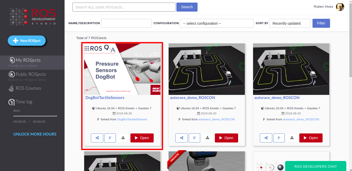
The first thing you need to do is to have a copy of the ROSject we mentioned above. Click on the link to get an automatic copy. You should now see a ROSject called DogBotTactileSensors on your list of ROSjects, something like the image below:
DogBot tactile sensors in ROSDS
After clicking on the Open button to open the ROSject, you should have the ROSject opened in a remote computer launched on ROSDS.
Launching the simulation
Once the ROSject is open, you can launch a simulation. You can achieve that in two ways:
Opening a web shell (clicking on Tools -> Web Shell) and typing: roslaunch dogbot_gazebo main.launch
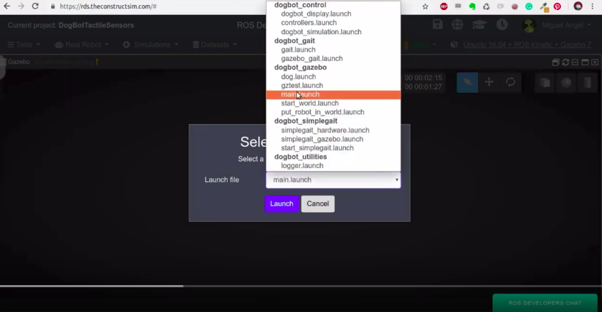
Using the menu Simulations -> Choose Simulation -> Choose Launch File. In the end, you will have a menu with a list of launch files. You can select the main.launch file in the dogbot_gazebo package as shown in the image below:
dogbot_gazebo main.launch in ROSDS
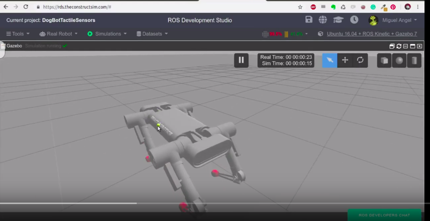
You should now have DogBot up and running in ROSDS:
dogbot robot running in ROSDS
In the simulation, you can see the robot has red “shoes” in its feet. There is where we put our pressure sensors.
Launching the simulation in your own local computer
The steps aforementioned are about how to launch the simulation in ROSDS (ROS Development Studio)
If you want to install in your local computer, you can just download the ROSject (or git clone) and execute requirements.sh script, which is located in the simulation_ws/src/dogbot_tc folder with the commands below:
cd simulation_ws/src/dogbot_tc

./requirements.sh
After that, you should be able to launch the simulation with:
source /opt/ros/kinetic/setup.bash
source simulation_ws/devel/setup.bash
roslaunch dogbot_gazebo main.launch
Listing the ROS Topics
Once you have the simulation up and running, you can see the contact sensors with:
rostopic list | grep contact
We can see that the topics are working by subscribing to a contact topic, using the command below:
If we look carefully at the data printed, we can see the frame_id “back_left_foot” and in the states section, you can see the objects the robot is in contact with and the forces applied.
Finding the code
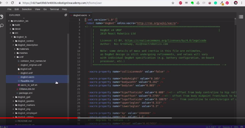
The code used to define the sensors is located in ~/simulation_ws/src/dogbot_tc/dogbot_description/urdf/dogbot.xacro
In ROSDS you can see it easily by using the Code Editor.
dogbot.xacro robot in ROSD
By looking at the code, if you find for “Contact Sensor” you will find it around line 350, inside the <gazebo> tag of the dogbot.xacro file.
Going deeper into the code
On the dogbot.xacro file, the sensor is defined in line 350 like below:
You can see the contact sensors in RViz. For that you can run the following command in a webshell:
rosrun dogbot_markers arrows_rviz.py
In a different shell you run:
rosrun rviz rviz
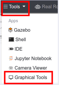
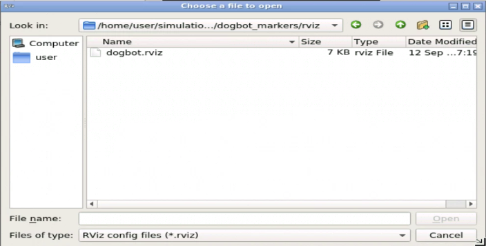
Open the Graphical Tools and select the rviz file inside the ~/simulation_ws/src/dogbot_tc/dogbot_markers/rviz folder. For that you first need to click Tools -> Graphical Tools, then select the rviz config file.
Launching Graphical Tools in ROSDS
Select the rviz config file for dogbot
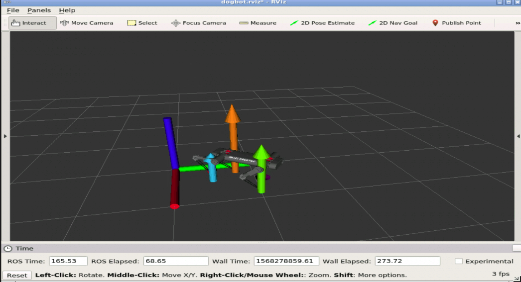
dogbot rviz sensors on ROSDS
Here the pressure in each of the feet of Dogbit is represented by an arrow, which lengths and colors are proportional to the pressure registered.
If you want a deeper understanding of how the markers are created and published in RViz, please have a look at the post on adding pressure sensors in RViz.
How to move DogBot
To move the robot you can easily use the command below:
Hit K to make DogBot stop, and to lower the speed, hit Z on the keyboard until when hitting I ( go forwards ) has a sable step. Around 0.1 is ok.
A video version of this post
So this is the post for today. If you prefer, we also have a video version of this post available in the link below. We hope you liked the post and the video. If so, please feel free to subscribe to our channel, share this post and comment on the video section.
We would like to thank React Robotics for this amazing robot and thank you for reading through this post.
Keep pushing your ROS Learning.
Interested in learning more? Try out this course on URDF creation for Gazebo and ROS:
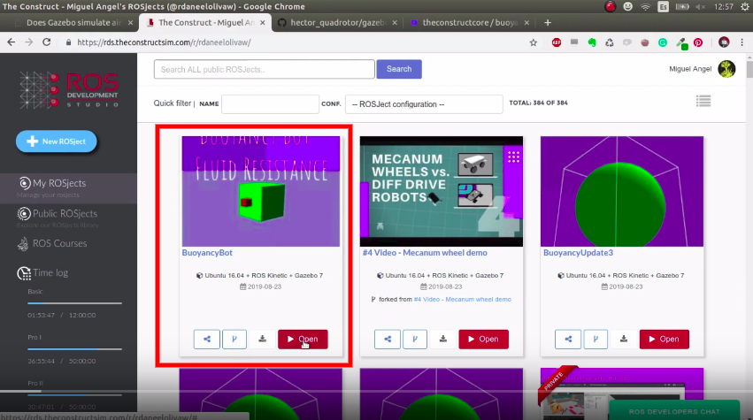
The first thing you need to do is to have a copy of the ROSject we mentioned above. Click on the link to get an automatic copy. You should now see a ROSject called BuoyancyBot on your list of ROSjects, something like the image below:
BuoyancyBot simulation on ROSDS
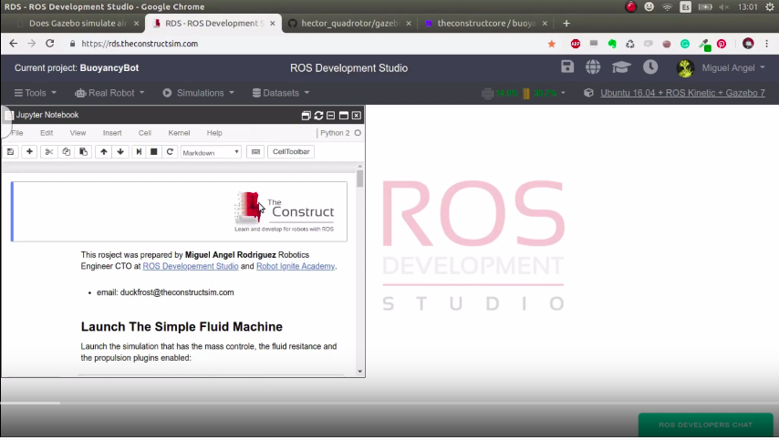
After clicking on the Open button to open the ROSject, you should have the environment like the one in the image below:
BuoyancyBot opened on ROSDS
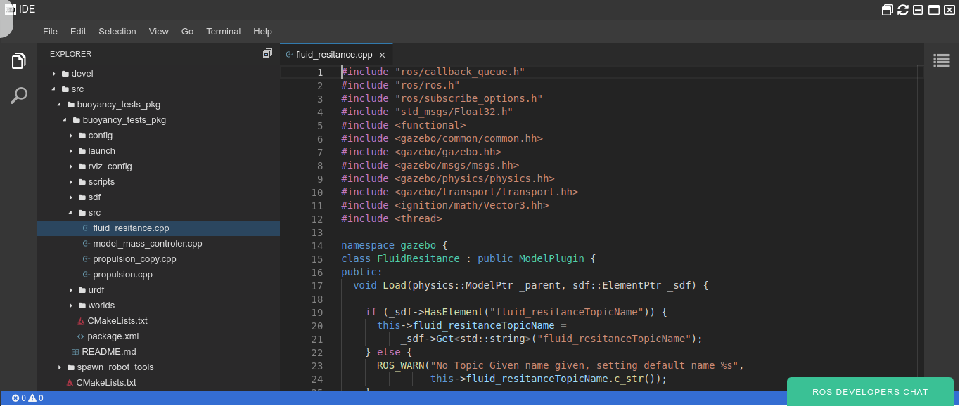
Finding the code
After opening the ROSject, you can see the code on the ~/simulation_ws/src folder. There you will find the folders buoyancy_tests_pkg and spawn_robot_tools. It is worth mentioning that the plugin we created is called fluid_resitance.cpp, which has the content below. Bear in mind that you can find that code on the ROSject:
#include "ros/callback_queue.h"
#include "ros/ros.h"
#include "ros/subscribe_options.h"
#include "std_msgs/Float32.h"
#include <functional>
#include <gazebo/common/common.hh>
#include <gazebo/gazebo.hh>
#include <gazebo/msgs/msgs.hh>
#include <gazebo/physics/physics.hh>
#include <gazebo/transport/transport.hh>
#include <ignition/math/Vector3.hh>
#include <thread>

namespace gazebo {
class FluidResitance : public ModelPlugin {
public:
  void Load(physics::ModelPtr _parent, sdf::ElementPtr _sdf) {

    if (_sdf->HasElement("fluid_resitanceTopicName")) {
      this->fluid_resitanceTopicName =
          _sdf->Get<std::string>("fluid_resitanceTopicName");
    } else {
      ROS_WARN("No Topic Given name given, setting default name %s",
               this->fluid_resitanceTopicName.c_str());
    }

    if (_sdf->HasElement("NameLinkToApplyResitance")) {
      this->NameLinkToApplyResitance =
          _sdf->Get<std::string>("NameLinkToApplyResitance");
    } else {
      ROS_WARN("No NameLinkToApplyResitance Given name given, setting default "
               "name %s",
               this->NameLinkToApplyResitance.c_str());
    }

    if (_sdf->HasElement("rate")) {
      this->rate = _sdf->Get<double>("rate");
    } else {
      ROS_WARN("No rate Given name given, setting default "
               "name %f",
               this->rate);
    }

    // Store the pointer to the model
    this->model = _parent;
    this->world = this->model->GetWorld();
    this->link_to_apply_resitance =
        this->model->GetLink(this->NameLinkToApplyResitance);

    // Listen to the update event. This event is broadcast every
    // simulation iteration.
    this->updateConnection = event::Events::ConnectWorldUpdateBegin(
        std::bind(&FluidResitance::OnUpdate, this));

    // Create a topic name
    // std::string fluid_resitance_index_topicName = "/fluid_resitance_index";

    // Initialize ros, if it has not already bee initialized.
    if (!ros::isInitialized()) {
      int argc = 0;
      char **argv = NULL;
      ros::init(argc, argv, "model_mas_controler_rosnode",
                ros::init_options::NoSigintHandler);
    }

    // Create our ROS node. This acts in a similar manner to
    // the Gazebo node
    this->rosNode.reset(new ros::NodeHandle("model_mas_controler_rosnode"));

#if (GAZEBO_MAJOR_VERSION >= 8)
    this->last_time = this->world->SimTime().Float();
#else
    this->last_time = this->world->GetSimTime().Float();
#endif

    // Freq
    ros::SubscribeOptions so = ros::SubscribeOptions::create<std_msgs::Float32>(
        this->fluid_resitanceTopicName, 1,
        boost::bind(&FluidResitance::OnRosMsg, this, _1), ros::VoidPtr(),
        &this->rosQueue);
    this->rosSub = this->rosNode->subscribe(so);

    // Spin up the queue helper thread.
    this->rosQueueThread =
        std::thread(std::bind(&FluidResitance::QueueThread, this));

    ROS_WARN("Loaded FluidResitance Plugin with parent...%s, With Fluid "
             "Resitance = %f "
             "Started ",
             this->model->GetName().c_str(), this->fluid_resitance_index);
  }

  // Called by the world update start event
public:
  void OnUpdate() {
    float period = 1.0 / this->rate;

    // Get simulator time
#if (GAZEBO_MAJOR_VERSION >= 8)
    float current_time = this->world->SimTime().Float();
#else
    float current_time = this->world->GetSimTime().Float();
#endif
    float dt = current_time - this->last_time;

    if (dt <= period){
        ROS_DEBUG(">>>>>>>>>>TimePassed = %f, TimePeriod =%f ",dt, period);
        return;
    }else{
        this->last_time = current_time;
        this->ApplyResitance();
    }


  }

public:
  void SetResitance(const double &_force) {
    this->fluid_resitance_index = _force;
    ROS_WARN("model_fluid_resitance_index changed >> %f",
             this->fluid_resitance_index);
  }

  void UpdateLinearVel() {
#if (GAZEBO_MAJOR_VERSION >= 8)
    this->now_lin_vel = this->model->RelativeLinearVel();
#else
    this->now_lin_vel = this->model->GetRelativeLinearVel();
#endif
  }

  void ApplyResitance() {

    this->UpdateLinearVel();

#if (GAZEBO_MAJOR_VERSION >= 8)
    ignition::math::Vector3d force, torque;
#else
    math::Vector3 force, torque;
#endif

    ROS_WARN("LinearSpeed = [%f,%f,%f] ",this->now_lin_vel.x, this->now_lin_vel.y, this->now_lin_vel.z);

    force.x = -1.0 * this->fluid_resitance_index * this->now_lin_vel.x;
    force.y = -1.0 * this->fluid_resitance_index * this->now_lin_vel.y;
    force.z = -1.0 * this->fluid_resitance_index * this->now_lin_vel.z;

    // Changing the mass
    this->link_to_apply_resitance->AddRelativeForce(force);
#if (GAZEBO_MAJOR_VERSION >= 8)
    this->link_to_apply_resitance->AddRelativeTorque(
        torque -
        this->link_to_apply_resitance->GetInertial()->CoG().Cross(force));
#else
    this->link_to_apply_resitance->AddRelativeTorque(
        torque -
        this->link_to_apply_resitance->GetInertial()->GetCoG().Cross(force));
#endif

    ROS_WARN("FluidResitanceApplying = [%f,%f,%f] ",force.x, force.y, force.z);
  }

public:
  void OnRosMsg(const std_msgs::Float32ConstPtr &_msg) {
    this->SetResitance(_msg->data);
  }

  /// \brief ROS helper function that processes messages
private:
  void QueueThread() {
    static const double timeout = 0.01;
    while (this->rosNode->ok()) {
      this->rosQueue.callAvailable(ros::WallDuration(timeout));
    }
  }

  // Pointer to the model
private:
  physics::ModelPtr model;

  // Pointer to the update event connection
private:
  event::ConnectionPtr updateConnection;

  // Mas of model
  double fluid_resitance_index = 1.0;

  /// \brief A node use for ROS transport
private:
  std::unique_ptr<ros::NodeHandle> rosNode;

  /// \brief A ROS subscriber
private:
  ros::Subscriber rosSub;
  /// \brief A ROS callbackqueue that helps process messages
private:
  ros::CallbackQueue rosQueue;
  /// \brief A thread the keeps running the rosQueue
private:
  std::thread rosQueueThread;

  /// \brief A ROS subscriber
private:
  physics::LinkPtr link_to_apply_resitance;

private:
  std::string fluid_resitanceTopicName = "fluid_resitance";

private:
  std::string NameLinkToApplyResitance = "base_link";

private:
#if (GAZEBO_MAJOR_VERSION >= 8)
  ignition::math::Vector3d now_lin_vel;
#else
  math::Vector3 now_lin_vel;
#endif

private:
  double rate = 1.0;

private:
  float last_time = 0.0;

private:
  /// \brief The parent World
  physics::WorldPtr world;
};

// Register this plugin with the simulator
GZ_REGISTER_MODEL_PLUGIN(FluidResitance)
} // namespace gazebo
Compile the plugin
Once you have the ROSject, be it on ROSDS or on your own computer, you can easily compile it with:
cd ~/simulation_ws/

catkin_make
Everything should have compiled without any problems. If compiling in your own computer raises errors, please remember running the command source /opt/ros/kinetic/setup.bash before calling catkin_make .
Using the plugin
The plugin we compiled previously has to be loaded by gazebo. We do that on the file
~/simulation_ws/src/buoyancy_tests_pkg/buoyancy_tests_pkg/urdf/simple_floating_sphere_buoyancy_control.urdf, by using the instructions below:
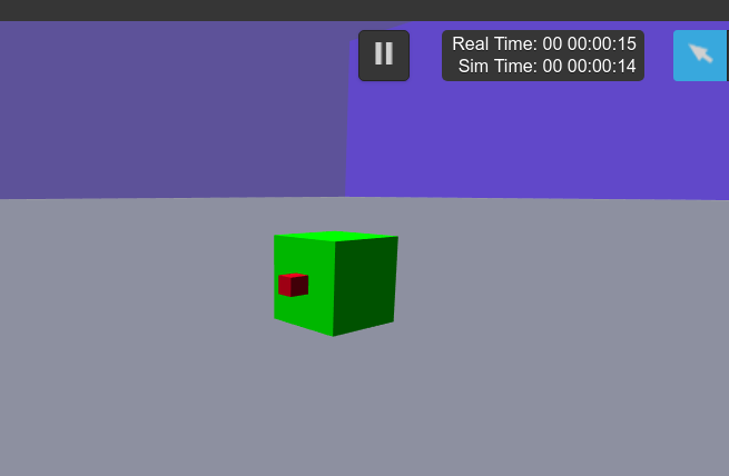
With everything in place, we can now run the simulation. To launch the Simple Fluid Machine, we launch the simulation that has the mass control, the fluid resistance and the propulsion plugins enabled:
If you have applied a movement and you change the FluidResistance, you should see a variation in the time the robot takes to stop. The higher the friction, the faster it will stop its movement.
Air Dragging in Gazebo on ROSDS
There is more to it but have a look at the HectorPluginsAerodinamics, in which this code is based upon.
Change the Mass or buoyancy
By changing the mass, it will change the buoyancy of the model. This is to simulate the water intake of submarines or the buoyancy system that an air flying machine like a blimp could have.
rostopicpub/model_massstd_msgs/Float32"data: 0.0"
Mass_0 = 7.23822947387 –> Neutral buoyancy because its the mass of the object
Mass > Mass_0 –> It will sink
Mass < Mass_0 –> It will rise
This mass you can find it in the URDF of the model: buoyancy_tests_pkg/urdf/simple_floating_sphere_buoyancy_control.urdf
So, that is the post for today. Remember that we also have a live version of this post on our YouTube channel, as can be seen on the link below. If you liked the content of this post or video, please consider subscribing to our channel and pressing the bell for a new video every single day:
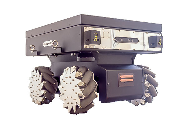
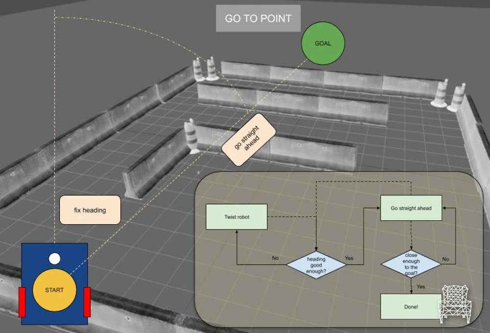
In this video, we’re going to compare our Mecanum Wheels to the simpler Diff Drive robot by using the standard “go to point” motion planning algorithm and an improved one
You will learn
Understand better the broad range of possibilities of mecanum wheels
Hey ROS developers! In this post, we start working on our own robotic manipulator. Based on the YouTube video series, we’ll show in this format the steps to achieve the final result of the series!
In this post number #1, I’m gonna show how to create the basic Unified Robot Description Format – URDF (the first two links) and visualize it in RViz!
Step 1 – Creating a package
I have here a fresh new ROSJect (which will be shared at the end of the post). Let’s start creating a package that will contain our robot description.
In a shell, execute the following command:
catkin_create_pkg mrm_description urdf
Now, we create a new folder, ~/simulation_ws/src/mrm_description/urdf, where we are gonna place the file mrm.xacro
XACRO files are “XML macros”, used to simplify URDF description.
Step 2 – Describing the robot
In order to create our robot, we must divide it into links and joints. This is what we are gonna do in our file.
Structure
The mandatory structure begins like:
<?xml version="1.0" ?>

<robot name="mrm" xlmns:xacro="http://www.ros.org/wiki/xacro">

  ...
  ... here goes the robot description
  ...

</robot>
First link
Let’s describe the first link, the base of the robot, it goes like this:
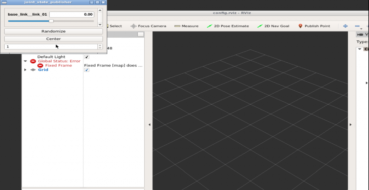
You can try launching it again to make sure the configurations we’ve just set will be loaded!
You can also play with the second window, the joint_state_publisher, in order to see the only movable joint changing position. Just drag the bar to left or right.
Related courses
URDF for Robot Modeling
ROS Manipulation
ROS for Industrial Robots
Conclusion
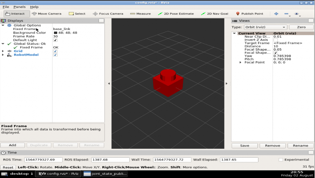
We have created the visual part of the robot!
In the next post, we’ll finish the other parts (link and joints) using XACROs, to make it simpler!
If you lost any part of the tutorial, you can get a copy of the ROSject I’ve done clicking here!
The ROSject contains the code of the following git: WhyDoINeedThis
Start the provided ROSject
The first thing you need to do is to copy the ROSject aforementioned. Click on the link to get an automatic copy.
Launch the ROSject
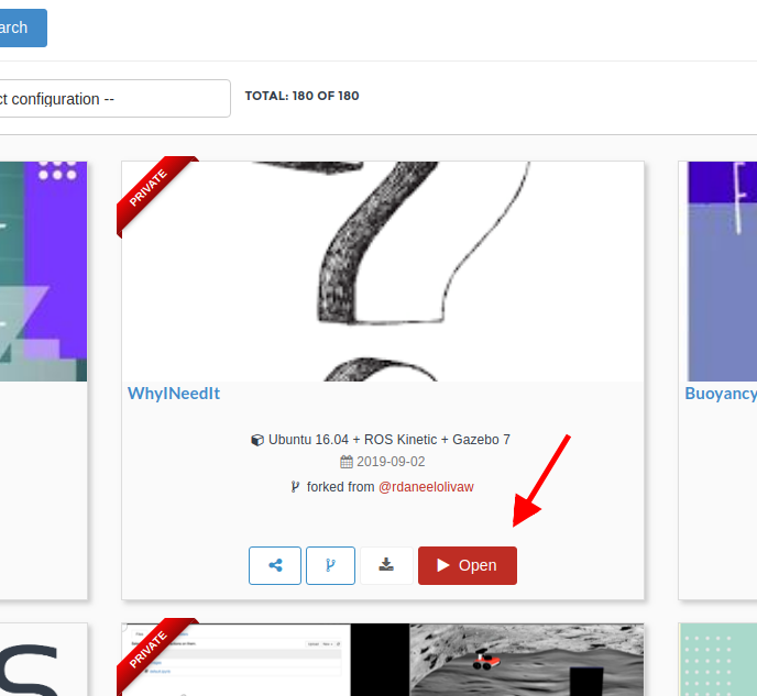
To launch the copied ROSject, go to your ROSDS account and click on the Open button of the copied rosject (see image below). Remember that the rosject you have to open is called WhyINeedIt.
why_python_Classes_rosject
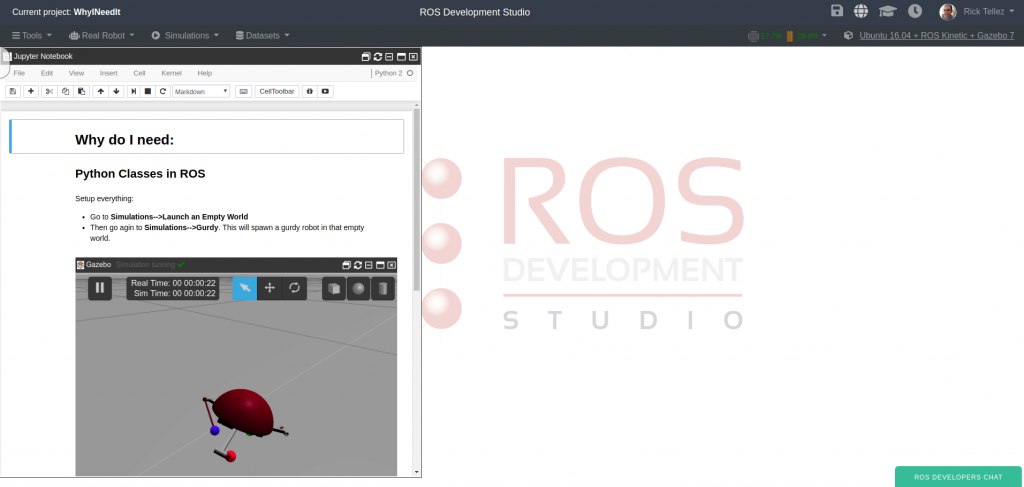
Once the rosject is open, you must see a screen like this:
python_rosject_open
At this point, you have succeeded in launching the ROSject.
Launch the simulation
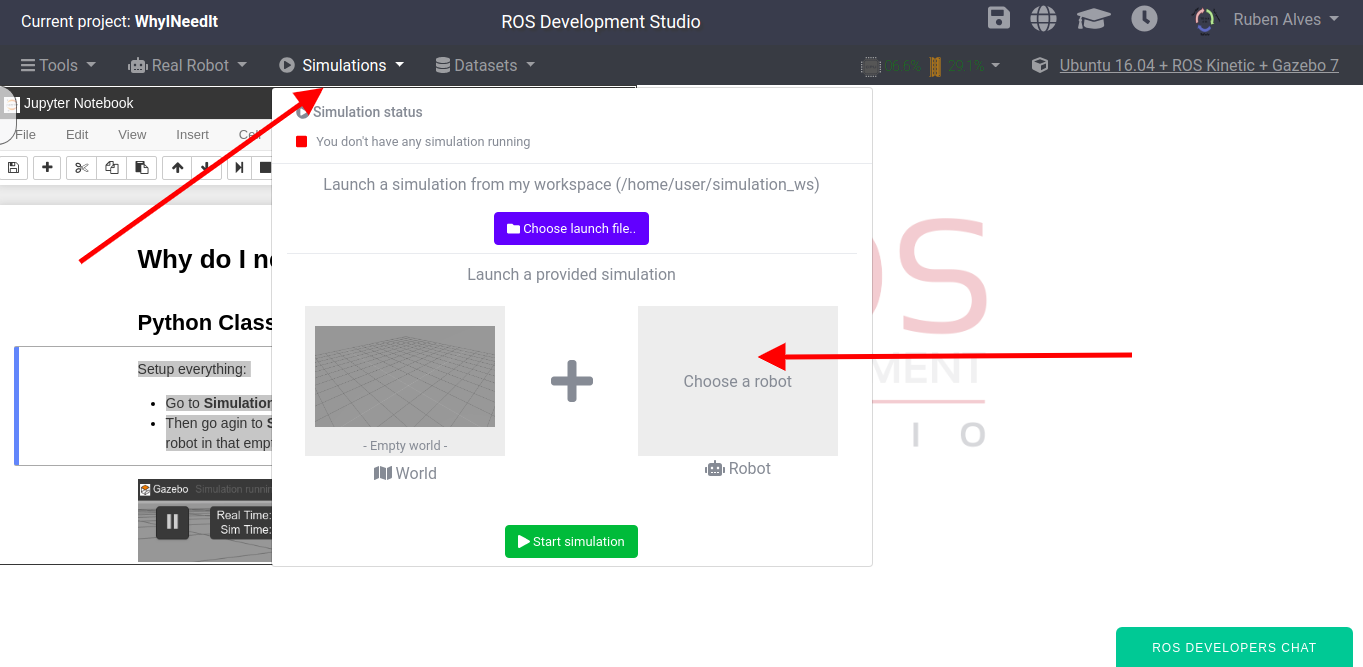
Let’s launch a simulation because we want a python class that detects when the robot is upside down. For that, let’s do the following:
Go to Simulations, then with the default empty world on the left, let’s click Choose a robot on the right side, as shown in the image below:
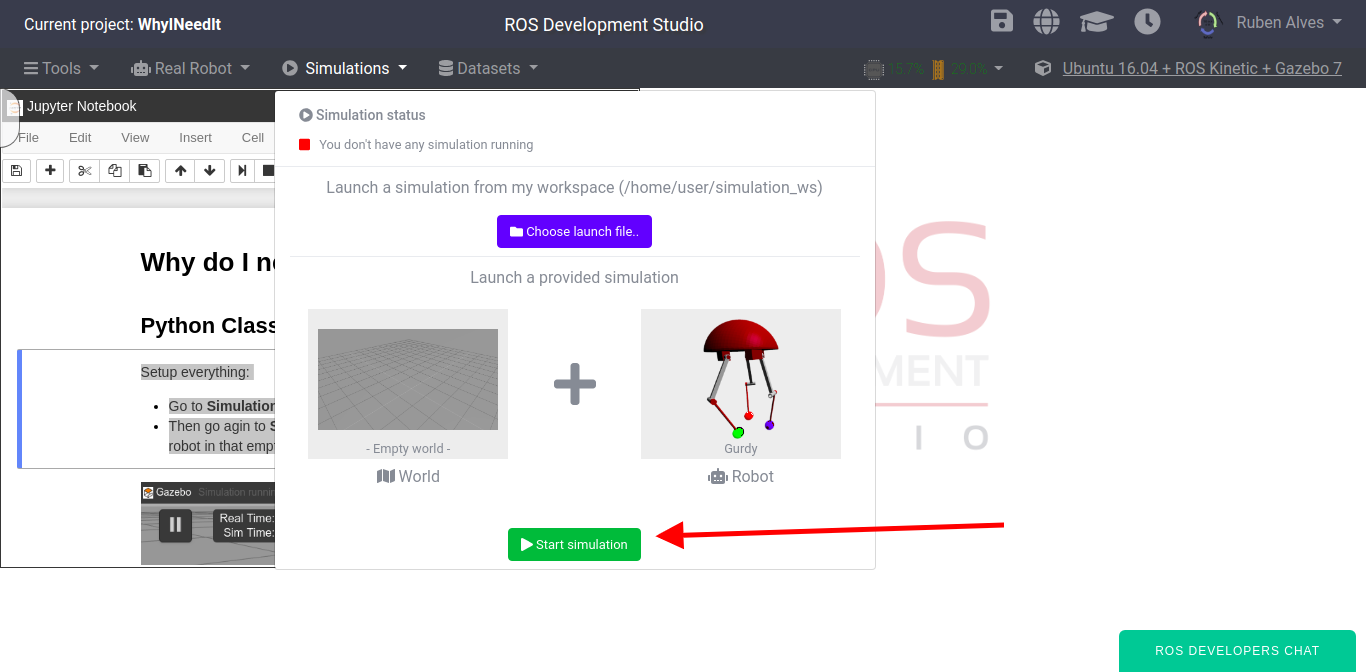
After that, you can type “gurdy” or try to find the Gurdy robot by using the scroll bar. Once the robot is selected, you just click Start Simulation.
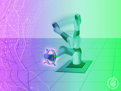
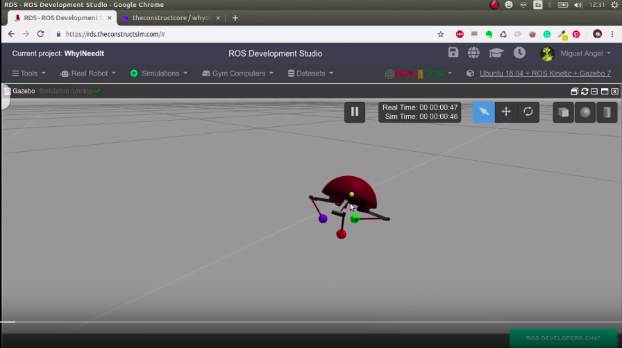
You now should see the simulation of the Gurdy robot as in the image below:
Finding the python code
The code used in this post can be found at ~/catkin_ws/src/. You can see the content with:
cd ~/catkin_ws/src/

ls
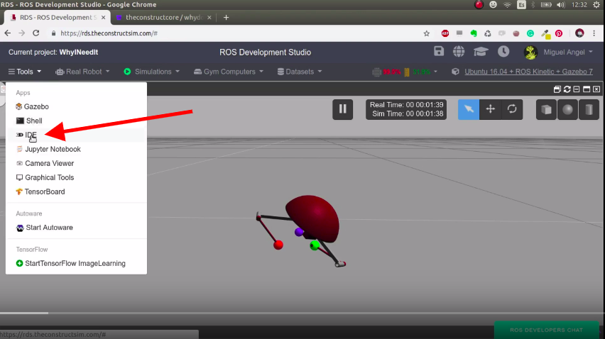
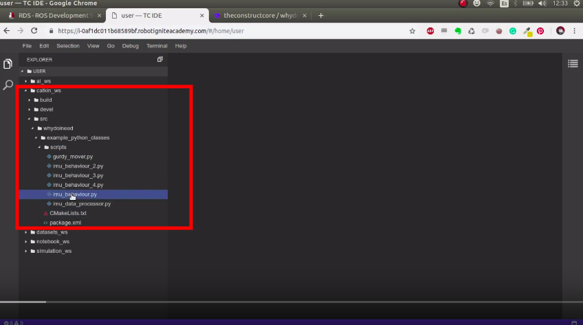
You can also find the code through the Code Editor. For that, let’s click Tools -> IDE as can be seen on the image below:
Once the IDE is open, we can find all the code that will be used to control the robot inside the catkin_ws folder (catkin workspace).
Detecting when the robot is upside down
In order to detect when the robot is upside down, we have to use the imu topic, which publishes the robot orientation. We can find the topic with the command rostopic list | grep imu :
user:~$ rostopic list | grep imu
/gurdy/imu/data
We see that the topic is named /gurdy/imu/data. We can see what is being published in this topic with rostopic echo -n1 /gurdy/imu/data , as exemplified below:
In the output above, we are more interested in the orientation, because is what tells us whether the robot is upside down or not.
In order to detect when the robot is upside down, we execute the imu_behaviour.py found on the catkin_ws with the command below:
rosrun example_python_classes imu_behaviour.py
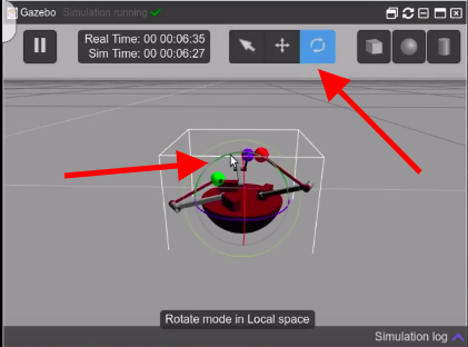
By manually turning the robot upside down, we can see in the output of this script that it correctly detects when that happens. In order to move the robot upside down, on gzweb (the simulation interface), you click on the “Rotate Mode“, then you rotate one of the arcs. In the example below, we rotate the green arc.
Gurdy upside down on ROSDS
Moving the robot to the right orientation automatically
When we detect that the robot is upside down, we have to move its legs, so that the robot can move back to the right position. The ROS topics we have to write to are 6 and can be found with rostopic list | grep command .
We have the script called imu_behaviour_2.py which automatically detects when the robot is upside down and publish on the topics listed above to have the robot back to normal position. The content of the file is the following:
The magic happens on the function get_imu_data shown above. Based on the position of the robot it decides which movement is going to be executed. We can execute the script with the command below:
rosrun example_python_classes imu_behaviour_2.py
With the command above running, if we now flip the robot around, it will automatically recover its position.
Optimizing the code
Although the imu_behaviour_2.py does the job it is proposed, everything is in a single file and publishers are created every time the execute_movement_gurdy function is called by the get_imu_data one. In addition to that, if we are working on a big project, it is better to have some people working on detecting when the robot is upside down, other people detecting on flipping the robot, so on and so forth.
To make this possible, it is better to have different python files, each one with its different class. We do that by creating the
GurdyBehaviour class on imu_behaviour_3.py, GurdyImuDataProcessor on imu_data_processor.py and
gurdyJointMover on gurdy_mover.py. With this structure, we could have different people working in each of the classes, having the Single Responsibility Principle.
With the classes split into different files, our code is easier to maintain. Please have a look at the different files to better understand the code and how to interacts with the robot.
You can test each script at a time. The more “optimized” version of our script is found on imu_behaviour_4.py which can be executed with:
rosrun example_python_classes imu_behaviour_4.py
So, that is the post of today. We hope you guys liked it. If so, please share this post with your friends.
Video with the explanation of this post
Remember that we also have a live version of this post, which can be found on the video below:
If you liked the video and the post, please leave your thoughts on the comments section of the video. You can also subscribe to our channel on YouTube and press the bell for a new video every day.
Did you like this video? Do you have questions about what is explained? Whatever the case, please leave a comment on the comments section below, so we can interact and learn from each other.
If you want to learn about other ROS topics, please let us know on the comments area and we will do a video about it 🙂
![[ROS Q&A] 192 – Add Pressure sensors in Gazebo Simulation for DogBot](https://www.theconstruct.ai/wp-content/uploads/2019/09/Add-Pressure-sensors-in-Gazebo-Simulation-for-DogBot.png)
![[ROS Q&A] 190 – Air Drag in Gazebo](https://www.theconstruct.ai/wp-content/uploads/2019/08/Air-Drag-in-Gazebo.png)
![[Robot Modeling] Comparing Mecanum Wheels with Diff Drive robots – Ep.4](https://www.theconstruct.ai/wp-content/uploads/2019/08/MECANUM-WHEELS-vs.-DIFF-DRIVE-ROBOTS-.png)

![[ROS Q&A] 191 – How to load a pre-built map into ROS for the Navigation Stack](https://www.theconstruct.ai/wp-content/uploads/2019/06/ROS-QA-191-How-to-load-a-pre-built-map-into-ROS-for-the-Navigation-Stack.jpg)