Basically what we are going to teach in this extra Live-Class is: 1- How to record a trajectory that you would like the robot to do 2- How to make the robot reproduce that trajectory
Everything using the GPS as localization system.
This time we are going to use the ROS Development Studio to do the practice. Please you need to have an account at RDS (free account is ok, and fully working). Please it is very important that attendants have the account created prior to the class so we do not waste time with that process.
All the attendants will receive a full notebook and code that does the two points. The notebook will explain step by step how the code works and where to change for another robot different than the one used in the simulation.
This is an Extra Live Class requested by the ROS Agriculture community (http://rosagriculture.org/), that is why we are doing this Live Class on Saturday (instead of Wednesday). This is an extra class. Wednesday Live Class are still on the schedule (check it out Wednesday schedule here: ROS LIVE-Classes).
In this ROS LIVE-Class we’re going to create a world in the Gazebo simulator for the previous differential drive manipulator we created in the previous class, so the robot can navigate around and interact with the objects.
The model of the robot was created using URDF. However, the model of the environment will be created using SDF.
We will see: ▸ How to create the world for the robot using SDF ▸ How to add models of any object you may think of ▸ How to spawn ROS based robots in the world
Part 1
Part 2
Every Wednesday at 18:00 CET/CEST.
This is a LIVE Class on how to develop with ROS. In Live Classes you practice with me at the same time that I explain, with the provided free ROS material.
IMPORTANT: Remember to be on time for the class because at the beginning of the class we will share the code with the attendants.
IMPORTANT 2: in order to start practicing quickly, we are using the ROS Development Studio for doing the practice. You will need a free account to attend the class. Go to http://rds.theconstructsim.com and create an account prior to the class.
In this ROS LIVE-Class we’re going to show how to create a Gazebo plugin for a robot simulated world. The plugin will allow us to connect/disconnect the light of the world by means of a ROS topic. The plugin will be created using C++.
We will use the simulation we created on the previous Live Class of a wheeled robot on a home room. Do not worry, you will receive the code of the simulation at the beginning of this Live Class (only provided to those who attend live to the class. The code will be provided during the first 5 minutes of the class, so be in time).
We will see: ▸ Which types of Gazebo plugins exist ▸ How to create a world plugin that allows you to control anything in the simulated world (very useful for Reinforcement Learning) ▸ How to add ROS to the plugin so we can use it from our ROS programs.
Every Tuesday at 18:00 CET/CEST. This is a LIVE Class on how to develop with ROS. In Live Classes you practice with the teacher in real time, at the same time that he explains the lesson with the provided free ROS material.
IMPORTANT: Remember to be on time for the class because at the beginning of the class we will share the code with the attendants.
IMPORTANT 2: in order to start practicing quickly, we are using the ROS Development Studio the practice. You will need a free account to attend the class. Go to http://rds.theconstructsim.com and create an account prior to the class. Otherwise you will not be able to practice during the class.
In this Live Class we are going to see how to apply all that we have learnt in the previous classes about Gazebo. We are going to execute ARIAC simulation made by the OSRF. We are going to learn how to manage that simulation in order to make the robots perform useful tasks in the environment. We will indicate where Gazebo plugins were applied, how SDF was used to create the environment, were ROS control was applied, where ROS navigation was applied, etc. We will see how to create a simple Python program that allows us to make the robots do useful things.
A new ROS Live Class every Tuesday at 18:00 CET/CEST. This is a LIVE Class on how to develop with ROS. In Live Classes you practice with me at the same time that I explain, with the provided free ROS material.
IMPORTANT: Remember to be on time for the class because at the beginning of the class we will share the code with the attendants.
IMPORTANT 2: in order to start practicing quickly, we are using the ROS Development Studio for doing the practice. You will need a free account to attend the class. Go to http://rds.theconstructsim.com and create an account prior to the class.
In this video we are going to see how to create a Python script that stops a robot if no message is received in the /cmd_vel topic after a certain period of time.
This is a video trying to answer the following question posted at the ROS answers forum.
In this video we are going to see how to configure the differential drive ROS controller for a wheeled robot using a Gazebo simulation.
This is a video trying to answer the question of Jaime posted at the ROS answers forum about how he cannot make the controller work, and receiving the error:
Controller Spawner couldn’t find the expected controller_manager ROS interface
Step1. Create Project
Let’s start with creating a new project in ROS development studio.
Notice: If you haven’t had an account yet. You can register one here for free.
Step2. Spawn a robot
As an example, we’ll use a self-build two-wheel differential drive robot.
You can test the code with your own robot with differential drive configuration.
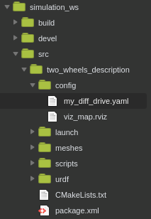
Step3. Add the controller configuration file for your robot
Put the configuration file(e.g. the my_diff_drive.yaml file shows here) under the config folder, your source tree may look like this.
Let’s start by pasting the whole code from the question into the my_diff_drive.yaml file.
mobile_base_controller:
  type        : "diff_drive_controller/DiffDriveController"
  left_wheel  : 'wheel_left_joint'
  right_wheel : 'wheel_right_joint'
  publish_rate: 50.0               # default: 50
  pose_covariance_diagonal : [0.001, 0.001, 1000000.0, 1000000.0, 1000000.0, 1000.0]
  twist_covariance_diagonal: [0.001, 0.001, 1000000.0, 1000000.0, 1000000.0, 1000.0]

  # Wheel separation and diameter. These are both optional.
  # diff_drive_controller will attempt to read either one or both from the
  # URDF if not specified as a parameter
  wheel_separation : 1.0
  wheel_radius : 0.3

  # Wheel separation and radius multipliers
  wheel_separation_multiplier: 1.0 # default: 1.0
  wheel_radius_multiplier    : 1.0 # default: 1.0

  # Velocity commands timeout [s], default 0.5
  cmd_vel_timeout: 0.25

  # Base frame_id
  base_frame_id: base_footprint #default: base_link

  # Velocity and acceleration limits
  # Whenever a min_* is unspecified, default to -max_*
  linear:
    x:
      has_velocity_limits    : true
      max_velocity           : 1.0  # m/s
      min_velocity           : -0.5 # m/s
      has_acceleration_limits: true
      max_acceleration       : 0.8  # m/s^2
      min_acceleration       : -0.4 # m/s^2
      has_jerk_limits        : true
      max_jerk               : 5.0  # m/s^3
  angular:
    z:
      has_velocity_limits    : true
      max_velocity           : 1.7  # rad/s
      has_acceleration_limits: true
      max_acceleration       : 1.5  # rad/s^2
      has_jerk_limits        : true
      max_jerk               : 2.5  # rad/s^3
Step4. Create Launch file
For our case, the launch file should look something similar like this.
The args for the controller should have the same name in the .yaml file which is “mobile_base_controller”
According to the .yaml file, there is no namespace /robot here, so we don’t need to add this to the controller node.
Things to make sure:
The left wheel and right wheel in the .yaml file should be the same as your robot’s URDF definition.
The gazebo controller should be added to the URDF definition as well as the transmission tag which will be used for the gazebo controller. In our case, we add the following code in the .urdf to add gazebo control in it.
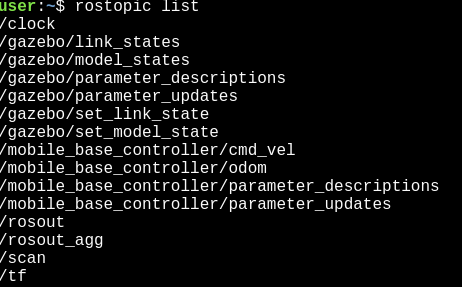
If you see the following topics, then your controller is up and run correctly.
Takeaway today:
The arg name of the controller node should be the same as in the controller configuration file.
Don’t specify robot namespace if you are not using it.
The joint name in the controller configuration file should be the same as the name in urdf
The gazebo_ros_control plugin should also be added to the urdf file.
Remember to compile again before you run.
If you want to learn more about ROS control and how to build a two-wheel robot in ROS from scratch, please visit Robot Ignite Academy for more information.

![[ROS Q&A] 126 – How to configure the differential drive ROS controller](https://www.theconstruct.ai/wp-content/uploads/2018/05/How-to-configure-the-differential-drive-ROS-controller.png)