In this series of videos we are going to learn how to use MoveIt! package with industrial robots. In this series we are going to use the Sawyer robot by Rethink Robotics.
Remember that you can follow all the steps with me at the same time by using the ROS Development Studio, without having to install anything in your system, and by using any operating system (yes, you can learn ROS with Windows!!!).
The instructions and steps provided here can be also made in your local computer with a proper installation of ROS.
[irp posts=”8707″ name=”Learning MoveIt! with Sawyer robot – #Part 1″]
// PART 2 VIDEO CONTENT
In this second video, we are showing: ▸ How to create the MoveIt! configuration package for Sawyer the robot, using the moveit_setup_assistant
▸ Previous video of this series (part 1) about how to install the Sawyer simulation: https://youtu.be/3wnX7teWIFQ
▸ Online course about how to learn to do ROS manipulation in 5 days, including grasping: https://goo.gl/v21WgA
ROS Manipulation is the term used to refer to any robot that manipulates something in its environment. The main goal of this Course is to teach you the basic tools you need to know in order to be able to understand how ROS Manipulation works, and teach you how to implement it for any manipulator robot.
We show you a manual method to tune a PID for a robot that uses ROS Control to control its joints with a position controller. This method is very artisan but it is enough for most of the cases.
We do not teach how ROS Control works in this video. We assume you already know how to configure a joint to work with the ROS controllers.
Step 1. Create a project in ROS Development Studio(ROSDS)
ROSDS helps you follow our tutorial in a fast pace without dealing without setting up an environment locally. If you haven’t had an account yet, you can create a free account here. Let’s call the testing.
Step 2. Tune PID
At first, let’s launch the rrbot simulation from Simulations->RRBot. To control the robot, we also need to launch the control with
roslaunch rrbot_control rrbot_control.launch
You will have to tune the pid value in the rrbot_contorl.yaml file in the rrbot_control package under the config.
We can also use rqt_gui to help us tune the parameter.
rosrun rqt_gui rqt_gui
Then open the Tools->graphical tool.
In the gui, let’s send command to the rrbot/joint1_position_controller/command topic to control the robot. The message type is automatically selected to std_msgs/Float64. We’ll change the frequency to 50 Hz, then click +.
Then click the + on the left to unfold the topic and change the expression to sin(i/50)*0.5. Check the box on the left side to start publishing into the topic.
You should see the robot starts to swing it’s arm now.
It’s also possible to plot the message from Plugins->Visualization->Plot
Select the correct topic /rrbot/joint1_position_controller/state/process_value/data then click +. You should see the data sent.
How about the actual value? It’s in the topic /rrbot/joint1_position_controller/state/process_value.
You’ll see that the actual state of the robot didn’t follow the command sent to the robot. That’s the reason why we need to tune the pid value.
Let’s open another tool to help us tune the value at the same time. Go to Plugins->Configuration->Dynamic Reconfigure.
You can change all the pid value in the plugin.
To tune the pid:
We start by increasing the p value to make the controller output more to catch the command.
Increase the d value a bit to make the movement smoother.
You should see the state can synchronize with the command now. You can change the command to see if the controller can follow the command nicely. Then you can save the value in the rrbot_controller.yaml file.
Remember, you have to launch the controller again to apply the new value.
If you need to understand better ROS Control, please take the following course for fast understanding:
You only need the raw basic files and the rest is automatically generated for you. Classify the Images with ImageLabel See the training progress with inbuild Tensorboard
After logging in RDS, click on Create New Project. If you haven’t had an account yet, you can create a free account with this link.
Step 2. Prepare model and training config file
This project is all about AI, we’ll put all the file we need into the au_ws. In this tutorial, we’ll show you this process with an already prepared for convenience. If you want, you can always generate the file you need by yourself. Let’s get started by moving into the directory and clone the project files.
$ cd ~/ai_ws
$ git clone https://bitbucket.org/theconstructcore/course_tflow_image_student_data.git
You can configure training settings with a .config file. Take ssd_mobilenet_v1_coco.config as an example, you can change the batch size here to make the training much faster. With a free account, you’ll have limited computational power and time in RDS which makes it very hard to run a long training session. If you need more computational power and time to train with a larger model with a larger batch size, please check our paid program.
We’ll only keep the files we need and delete the others.
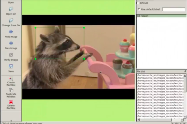
To train a deep learning model, you need to label the data first. In the project you just cloned, you can find the labeled image. You can also label your own image with the labeling tool in RDS. To use it, type in the shell
$ labelImg
then open the graphical tool, you can find it under the tools tab. If the command is not working, you can also download the tool from here.
You can draw bounding boxes and generate labeling for images with this tool.
Step 4. Training
Now you have all the files you need to train your model(labeled images, model, config file)! We created a tool in RDS to make the process even easier. Please go to tools -> start tensorflow image learning and select the files you’ve prepared. Then the training starts automatically and you can visualize it with the tensorboard tool! You can see the loss is reducing over time.
Step 5. Run the trained model
After the training is done, you can click tools -> stop image learning… to export frozen_graph file to the ai_ws. With this file, you can run the model and perform image recognition on the images.
If you are interested in this topic, please check our courses on robotic ignite academy for more information.
We show you how you can launch two drones (or more) in the same Gazebo simulation, each one having its own independent control system based on ROS. This procedure can be replicated to launch as many drones as required.
RELATED LINKS
– How to start programming drones with ROS: https://youtu.be/f7b5tSZW1Ig – Hector Quadrotor Simulation: https://bitbucket.org/theconstructcore/hector_quadrotor_sim – ROS Development Studio: https://goo.gl/Yf2Q4J
[irp posts=”6638″ name=”ROS Q&A | How to Start Programming Drones using ROS”]
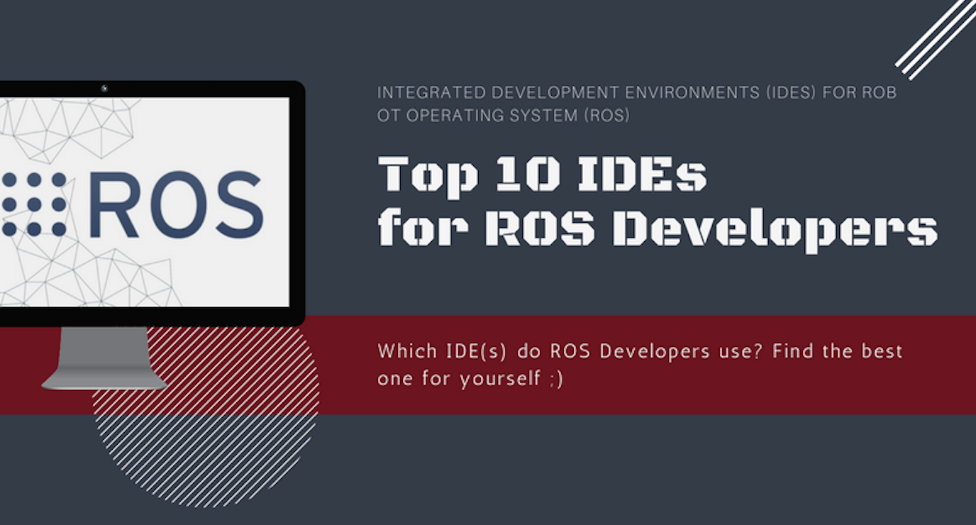
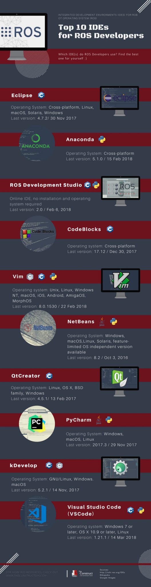
There is no best IDEs, only the IDE that works best for you. This infographic lists the 10 most commonly used IDEs, according to your needs to choose the most suitable Integrated Development Environments (IDEs) for you.
This video shows step by step how to build your own custom ROS service message, and how to use it in your own service.
For this example we will create a service that measures the amount of distance that the BB8 robot has moved. The service that we will provide is able to measure the amount of distance moved and provide that data either in meters or in miles, depending on how the request is done.
![[ROS Tutorials] TensorFlow Image Recognition in 5 Steps with ROS Development Studio](https://www.theconstruct.ai/wp-content/uploads/2018/03/TensorFlow-Image-Recognition-in-5-Steps-with-ROS-Developement-Studio.png)
![[ROS Q&A] 109 – How to create a custom ROS service message. BB-8 Gazebo Simulator](https://www.theconstruct.ai/wp-content/uploads/2018/03/How-to-create-a-custom-ROS-service-message-screen.png)