URDF Inertia for Gazebo – Introduction
Hey ROS developers! In this post, we will make our robot able to be spawned into Gazebo simulator. Based on the YouTube video series, we’ll show in this format the steps to achieve the final result of the series!
In this post number #3, I’m gonna create the Inertia properties to each of our links using the same XACROs files we have been working with. Up to the end of the post, we’ll have the complete model of the robot inside a Gazebo world!
Step 1 – Adding Inertial and Collision properties – Adjust XACRO file
The first part of this modification is adding some new properties to the links we already have.
Let’s open the file ~/simulation_ws/src/mrm_description/urdf/links_joints.xacro
There we have 3 XACROs being defined, one for joints and 2 others for links. The links are the ones we need to adjust:
Cylinder links
The first one, the macro called m_link_cylinder, this is how it must look like, after the adjustments:
<xacro:macro name="m_link_cylinder" params="name origin_xyz origin_rpy radius length mass ixx ixy ixz iyy iyz izz">
    <link name="${name}">
    <inertial>
        <mass value="${mass}" />
        <origin rpy="${origin_rpy}" xyz="${origin_xyz}" />
        <inertia ixx="${ixx}" ixy="${ixy}" ixz="${ixz}" iyy="${iyy}" iyz="${iyz}" izz="${izz}" />
    </inertial>
    <collision>
        <origin rpy="${origin_rpy}" xyz="${origin_xyz}" />
        <geometry>
            <cylinder radius="${radius}" length="${length}" />
        </geometry>
    </collision>
    <visual>
        <origin rpy="${origin_rpy}" xyz="${origin_xyz}" />
        <geometry>
            <cylinder radius="${radius}" length="${length}" />
        </geometry>
    </visual>
    </link>
</xacro:macro>
We added the inertial property, the one in charge of passing the mass and inertia values, from a real or project of a robot we have, to the simulator. These values are going to be used by the physics calculator of Gazebo.
And the collision property is used to calculate when an object collides to another during the simulation. Important to notice its values are the same of the visual part. That’s because we have a simple visual part for these links. It happens to have different values for visual and collision when we want to simplify the collisions for a more complex mesh we may have for a joint (we’ll have an example up to the end of the series).
Finally, don’t forget (if you are copying the new values manually) to notice the new params values we have added to the definition of the tag xacro:macro.
Box links
And for the second type of links we have, the box one. We need to do very similar modifications, but quite different parameters, due to the kind of shape we have now.
The macro must look like:
<xacro:macro name="m_link_box" params="name origin_xyz origin_rpy size mass ixx ixy ixz iyy iyz izz">
    <link name="${name}">
        <inertial>
            <mass value="${mass}" />
            <origin rpy="${origin_rpy}" xyz="${origin_xyz}" />
            <inertia ixx="${ixx}" ixy="${ixy}" ixz="${ixz}" iyy="${iyy}" iyz="${iyz}" izz="${izz}" />
        </inertial>
        <collision>
            <origin rpy="${origin_rpy}" xyz="${origin_xyz}" />
            <geometry>
            <box size="${size}" />
            </geometry>
        </collision>
        <visual>
            <origin rpy="${origin_rpy}" xyz="${origin_xyz}" />
            <geometry>
            <box size="${size}" />
            </geometry>
        </visual>
    </link>
</xacro:macro>
Again, we have added new parameters to the macro tag, which are in the value of the params attribute.
And added the inertial and collision tags, for the very same reason.
Step 2 – Adjusting the main XACRO file – mrm.xacro
Let’s open the main file we have to describe the entire robot: ~/simulation_ws/src/mrm_description/urdf/mrm.xacro
The changed we need to do are related only the new parameters we added to the MACROs. The worst part is that we’ll do one by one (which is the most important part when you have many different links from a real robot). Let’s start!
Base_link
Starting from the base_link (or ${link_00_name}, the one which is a box):
<m_link_box name="${link_00_name}"
           origin_rpy="0 0 0" origin_xyz="0 0 0"
           mass="1024"
           ixx="170.667" ixy="0" ixz="0"
           iyy="170.667" iyz="0"
           izz="170.667"
           size="1 1 1" />
The values used to fill the 7 new parameters were taken from a CAD software. It’s not something we will cover in this series, we are just bringing pre-calculated values to the practical part of simulating a robot.
Link_01
For the next link named link_01 (or ${link_01_name}), let’s do the same (very similar, at least):
<m_link_cylinder name="${link_01_name}"
           origin_rpy="0 0 0" origin_xyz="0 0 0.2"
           mass="157.633"
           ixx="13.235" ixy="0" ixz="0"
           iyy="13.235" iyz="0"
           izz="9.655"
           length="0.4" radius="0.35" />
The next 3 links (_02, _03 and _04)
These links will have the same values, so let’s do it just once:
<m_link_cylinder name="${link_0X_name}"
         origin_rpy="0 0 0" origin_xyz="0 0 0.4"
         mass="57.906"
         ixx="12.679" ixy="0" ixz="0"
         iyy="12.679" iyz="0"
         izz="0.651"
         radius="0.15" length="0.8" />
(Pay attention to the name property if you are copying and pasting!!)
The final link
And the values for the final link:
<m_link_cylinder name="${link_05_name}"
        origin_rpy="0 0 0" origin_xyz="0 0 0.125"
        mass="18.056"
        ixx="0.479" ixy="0" ixz="0"
        iyy="0.479" iyz="0"
        izz="0.204"
        radius="0.15" length="0.25" />
Step 3 – Opening it in RViz
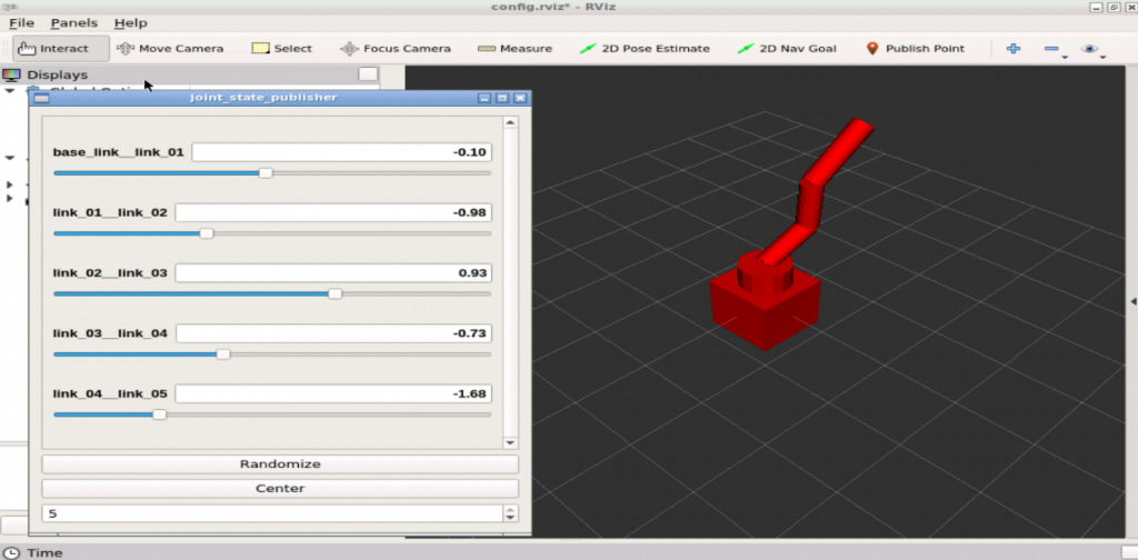
Just before trying to simulate it, let’s make sure we didn’t break anything we had before. Let’s open it in RViz, using the same launch file we used before:
From a web shell, execute the following:
roslaunch mrm_description rviz.launch
And you must have a screen like the one below:
Great!
Step 4 – Creating a launch file
Before anything related to the simulation, we need a launch file to spawn the robot. Let’s create one:
The file will be ~/simulation_ws/src/mrm_description/launch/spawn.launch
<?xml version="1.0" encoding="UTF-8"?>
<launch>
    <param name="robot_description" command="$(find xacro)/xacro --inorder '$(find mrm_description)/urdf/mrm.xacro'" />

    <arg name="x" default="0" />
    <arg name="y" default="0" />
    <arg name="z" default="0.5" />

    <node name="mybot_spawn" pkg="gazebo_ros" type="spawn_model" output="screen"
          args="-urdf -param robot_description -model mrm -x $(arg x) -y $(arg y) -z (arg z)" />
</launch>
Step 5 – Spawning the robot into a simulation
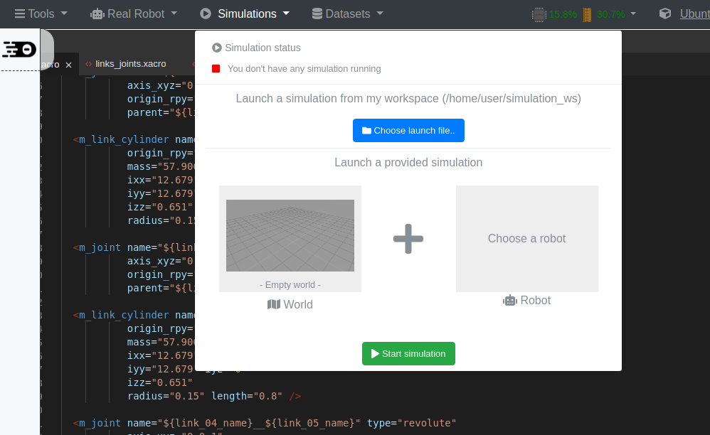
Let’s start an empty simulation from the menu:
And from a web shell, let’s spawn the robot:
<?xml version="1.0" encoding="UTF-8"?>
<launch>
    <param name="robot_description" command="$(find xacro)/xacro --inorder '$(find mrm_description)/urdf/mrm.xacro'" />

    <arg name="x" default="0" />
    <arg name="y" default="0" />
    <arg name="z" default="0.5" />

    <node name="mybot_spawn" pkg="gazebo_ros" type="spawn_model" output="screen"
          args="-urdf -param robot_description -model mrm -x $(arg x) -y $(arg y) -z $(arg z)" />
</launch>
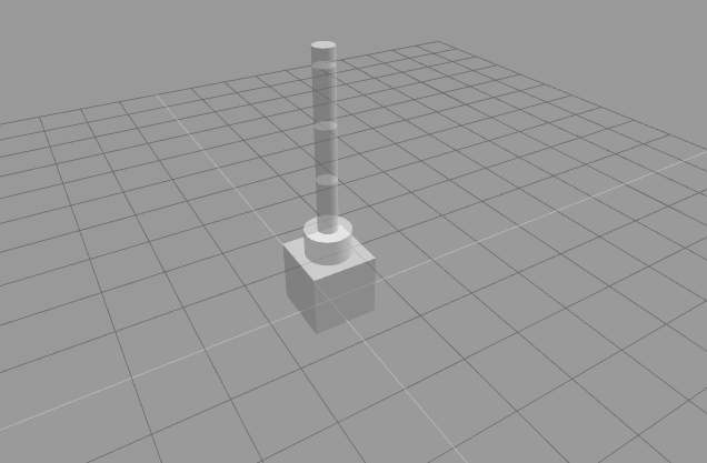
And your gazebo simulation must look like below:
After some seconds the robot will “fall down”, that’s because we didn’t aplly any controllers to the joints. (Which is something for the next post!!)
Related courses
Conclusion
We have created the collision and inertial parts of the robot using our XACROs! It was easy!!
In the next post, we’ll apply gazebo controllers to the robot. A very important step to have it working and controlled by our ROS programs!!
If you lost any part of the tutorial, you can get a copy of the ROSject I’ve done clicking here!
See you!





0 Comments